
Heat sink

a heat sink and heat sink technology, applied in the direction of electrical equipment construction details, lighting and heating apparatus, laminated elements, etc., can solve the problems of limited practical fin height, limited overall thermal performance of one-piece extruded heat sinks of this type, and limited practical manufacturing considerations. , to achieve the effect of high thermal and mechanical performance and low manufacturing cos

Inactive Publication Date: 2007-04-05
DAU GMBH & CO KG
View PDF10 Cites 37 Cited by
  • Summary
  • Abstract
  • Description
  • Claims
  • Application Information

AI Technical Summary

Benefits of technology

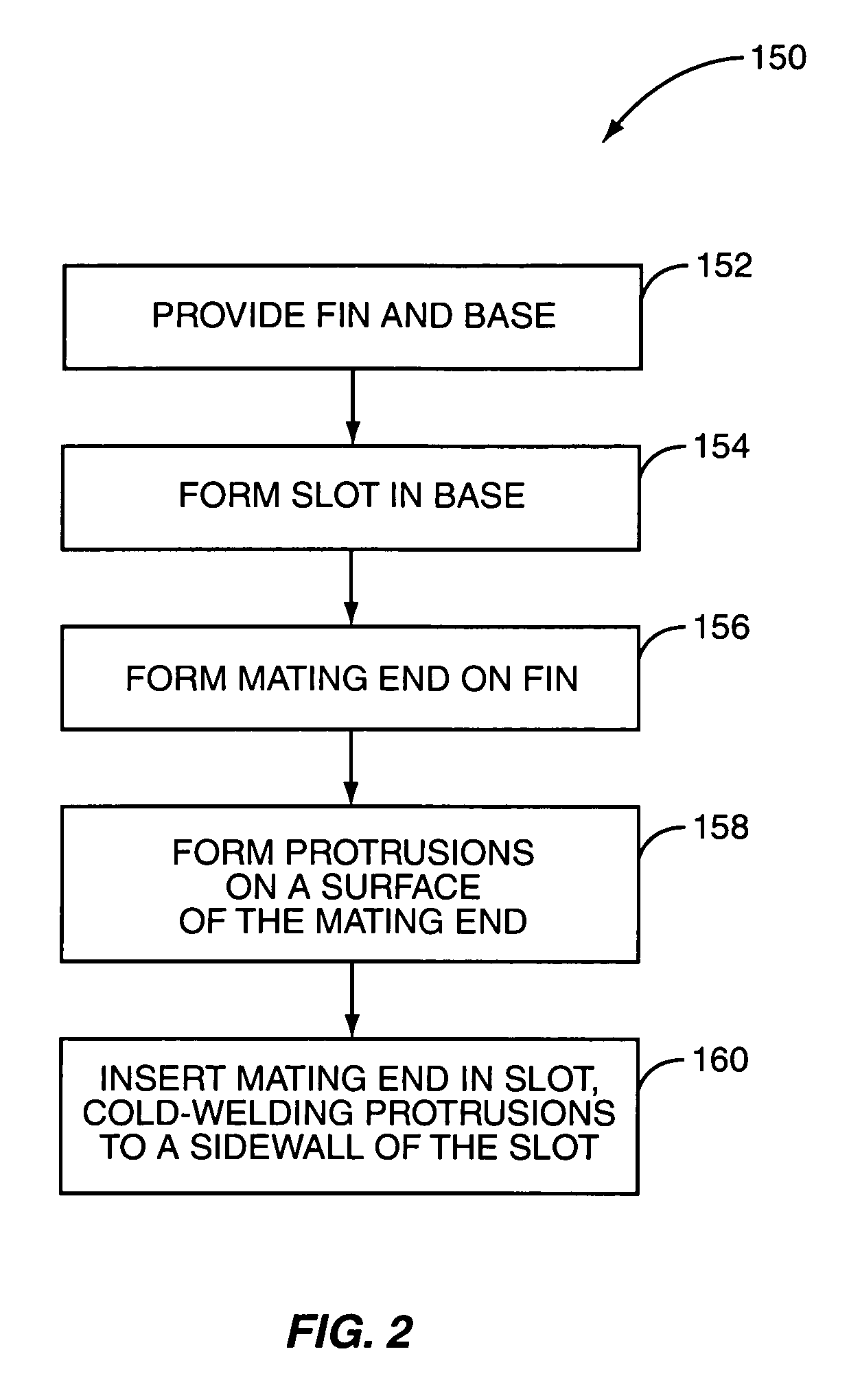
[0015] The methods and apparatus taught herein provide a heat sink manufacturing and assembly process offering low manufacturing costs and yielding a heat sink with high thermal and mechanical performance. According to one embodiment, a heat sink assembly comprises a base having a slot and a fin. The slot has first and second sidewalls and the fin has an end adapted for insertion in the slot, wherein the fin end comprises a first surface configured to conformally engage the first sidewall during insertion for thermal bonding and a second surface having one or more protrusions configured to cold-weld to the second sidewall during insertion for mechanical fastening. As used herein, and unless otherwise noted, the term “conformally engage” implies a contoured surface-to-surface contact between adjacent objects.

Problems solved by technology

However, the actual cost effectiveness and operating performance of convection heat sinks depends on a potentially complex set of variables, including heat sink material selection and base / fin fabrication details.
However, the overall thermal performance of one-piece extruded heat sinks of this type is limited by practical manufacturing considerations.
Namely, the practical fin height is limited by extrusion limitations, such as the fin height-to-thickness aspect ratio (e.g., 20:1 maximum).
However, increasing the aspect ratio compromises extrusion tolerances.
Practical manufacturing considerations of this sort generally limit the thermal performance of one-piece extruded heat sinks to heat dissipation to less than 12 W / in.2 maximum.
However, the two-piece approach presents the two-fold challenge of establishing good thermal conduction at the base-fin connections while maintaining requisite base-fin mechanical strength.
Overall, the precision and finishing required in this process makes it relatively expensive in comparison to other methods.
However, thermal performance is heavily dependent on the bonding material, which itself can be expensive, and trade-offs exist between the thermal and mechanical performance of the bonding material.
While this process produces good mechanical bonding, the irregular (non-conformal) contact between fin and base caused by the cold-welding ridges limits the thermal performance (in the range of 25-26 W / in.2).
However, folded fin assemblies generally suffer significant pressure drop in forced air convection applications, and do not offer good natural convection, leading to potentially serious problems in the event of fan failure.
With these complexities in mind, it will be appreciated that building a high performance heat sink represents a rather complicated design challenge.

Method used


Image

  • Heat sink
  • Heat sink
  • Heat sink

Examples


Embodiment Construction

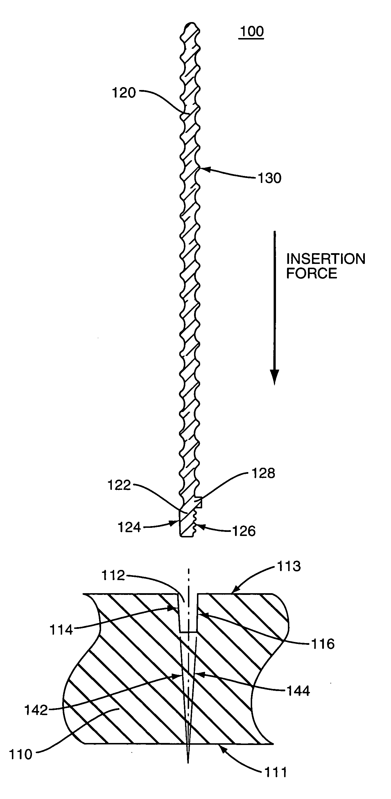
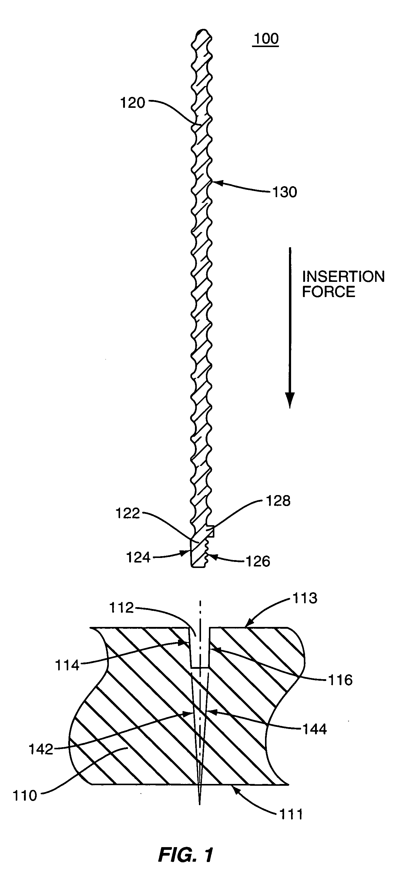
[0029]FIG. 1 illustrates in a partial cross-sectional view components comprising one embodiment of a low-cost, high thermal performance convection heat sink assembly as taught herein. The heat sink assembly 100 comprises the base 110 and the fin 120. The base 110 and the fin 120 can comprise any material having suitable thermal conductivity such as aluminum, copper, silver, or any suitable alloy or combination thereof. Preferably, the base 110 and the fin 120 comprise an aluminum alloy such as AlMgSiO5, and may be advantageously formed using an extrusion process.

[0030] The base 110 is configured to dissipate heat from an electronic component (not shown) when the electronic component is in contact with the lower surface 111 of the base. The fin 120 is configured to dissipate heat from the base 110 when the fin is inserted into the base. The base 110 includes a slot 112 formed therein for receiving the fin 120. The slot 112 extends upward toward an upper surface 113 of the base 110 a...


PUM


Abstract

A heat sink assembly comprises a base having one or more slots, and further comprises one or more fins, each having an end configured for insertion into a respective one of the slots. Each fin end has a first surface that is configured for conformally engaging a first slot sidewall for good thermal conduction from the base into the fin, and has a second surface configured for cold welding to a second slot sidewall for good mechanical fastening of the fin to the base. The combined thermal bonding and cold-welding engagement are produced by pressing the fin ends of the fins into the base slots at a controlled pressing rate. Further, leading and / or trailing edges of the fins may be beveled to improve airflow directed edgewise across the fins.

Description

BACKGROUND OF THE INVENTION [0001] The present invention relates to heat sinks, and particularly relates to convection heat sinks, such as may be used for semiconductor cooling. [0002] Heat sinks are widely used to enhance the removal of heat energy from various types of electronic components. For example, heat sinks are pervasively used to cool semiconductor devices such as microprocessors, memory circuits, lasers, charge-coupled devices, and power electronics such as insulated gate bipolar transistors (IGBTs), etc. [0003] Selection of an appropriate heat sink is determined by the specific thermal load to be dissipated. The chosen heat sink must withstand the maximum heat load applied by the component to be cooled while not exceeding the maximum temperature specified by the component supplier / manufacturer. Various classes of heat sinks are available depending on the thermal load requirements. For example, convection heat sinks (both natural and forced air), liquid cooled heat sinks...

Claims


Application Information

Patent Timeline
Patent Type & Authority Applications(United States)
IPC IPC(8): H05K7/20
CPCF28F3/02F28F13/06H01L21/4882H01L23/367H01L23/467H01L2924/0002H01L2924/3011H01L2924/00F28F2215/10
Inventor PESCHL, HANS
Owner DAU GMBH & CO KG
Learn More