Methods for modifying surfaces

a surface modification and surface technology, applied in the field of surface modification methods, can solve the problems of difficult control of surface chemistry modification depth, many surface modification methods under development are not readily suited to industrial applications and scale up, and the current surface modification strategy does not meet these conditions

Inactive Publication Date: 2007-06-14
THE TRUSTEES OF COLUMBIA UNIV IN THE CITY OF NEW YORK
View PDF21 Cites 73 Cited by
  • Summary
  • Abstract
  • Description
  • Claims
  • Application Information

AI Technical Summary

Problems solved by technology

Most current surface modification strategies do not meet these conditions.
Few current techniques for surface modification, however, allow for specific chemical and structural control at molecular dimensions.
In addition, many methods under development for surface modification are not readily suited to industrial application and scale up.
Oxidative treatments, such as corona discharge, oxygen plasma, or UV / ozone are indiscriminate and kinetic in nature, rendering the control of modification depth of surface chemistry difficult.
These treatments are often unstable, and involve reorganization at the surface shortly after processing.
Chemical treatment methods for surface modification often require harsh and hazardous reagents, and the depth of modification can usually be confined to the surface only by regulating the exposure time.
Further, these techniques usually require expensive equipment and sophisticated process controls.
These techniques also involve safety hazards including electric shock, UV exposure, and laser exposure.
Further, these surface modification techniques result in non-homogenous surfaces that have multiple surface functional groups, which reduces their selectivity for subsequent derivatization.
These techniques are increasingly unacceptable from an environmental and safety perspective.
These techniques also have difficulties in modifying the surface uniformly and reproducibly.
However, several limitations are associated with each of these methods.
The resolution of the patterned area is limited only by the wavelength of the light, but existing techniques suffer from the usual requirement of a development step to create the pattern.

Method used


Image

  • Methods for modifying surfaces
  • Methods for modifying surfaces
  • Methods for modifying surfaces

Examples


example 1

[0179] 4 mg of polystyrene-b-poly(t-butyl acrylate) (6.4K-7K, Polymer Source) was inserted into a high-pressure cell in every experiment regardless of carbon dioxide pressure. The corresponding concentration was 0.1 mg / cm3. PS fibers were placed inside a microcentrifuge tube located inside the high-pressure cell. The cell was charged with CO2 to desired pressure using an ISCO pump (260D). The temperature of the cell was controlled at 40° C. PS fibers were characterized with XPS and SEM.

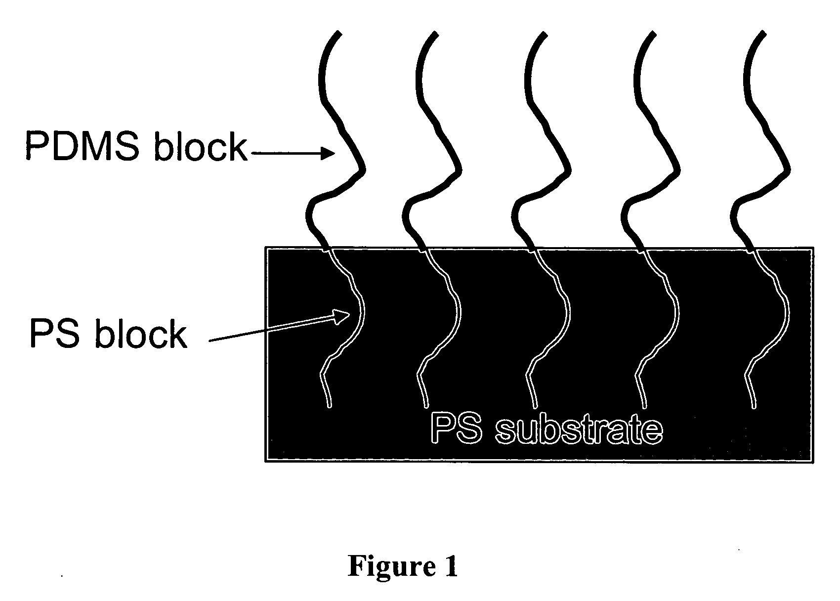
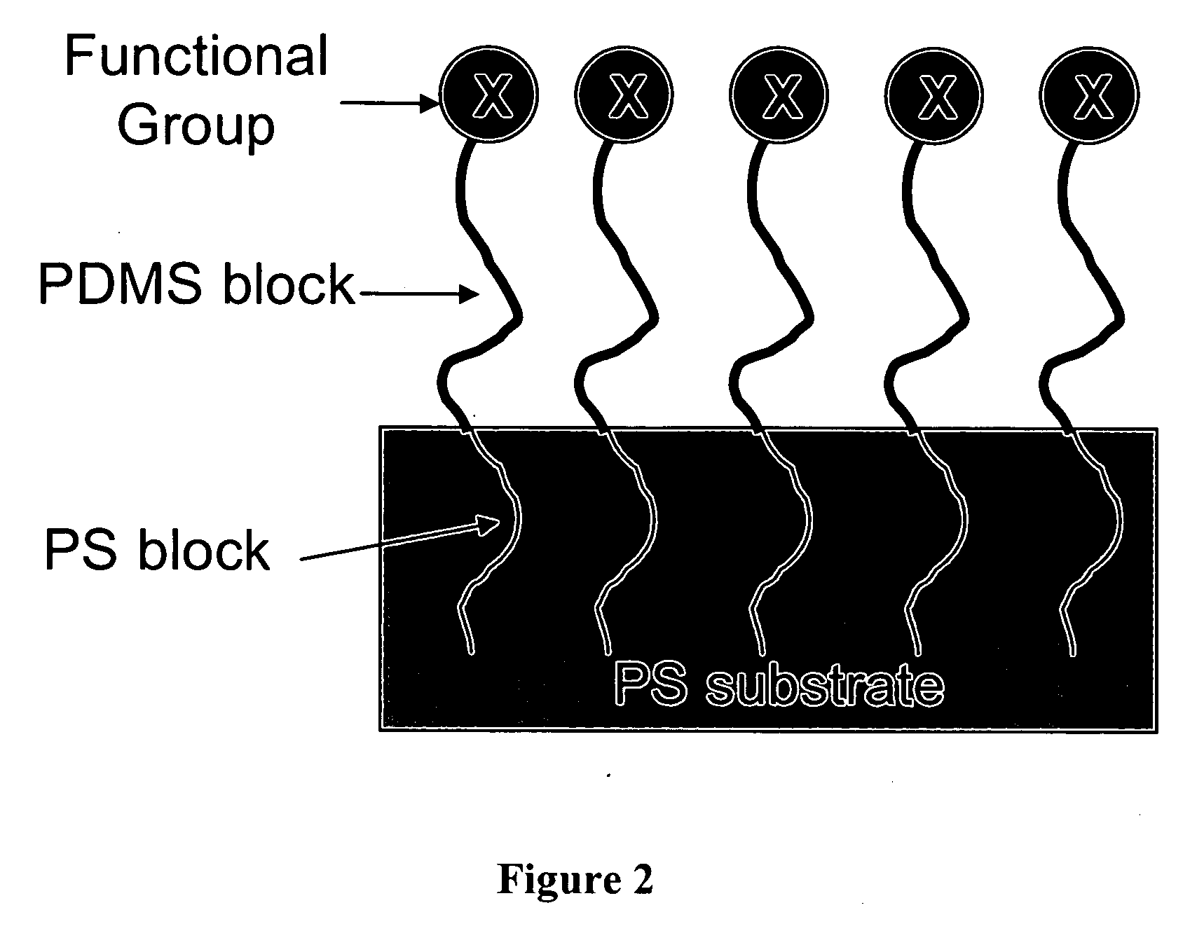
[0180] The block copolymer, PS-b-PtBA, starts to adsorb onto PS fibers when the pressure of CO2 is above 25 MPa. FIG. 5 shows that the surface coverage of PS-b-PtBA increases with the pressure of CO2. At 46 MPa, PS-b-PtBA totally covers the surface. FIG. 6 gives the SEM images of PS fibers before and after covering with block copolymer. The original PS fibers have small pores at the surface. After coating, the pores disappeared and very smooth surfaces were obtained.

[0181] The adsorption kinetics of...

example 2

[0182] 1 mg of polystyrene-b-poly(t-butyl acrylate) (6.4K-7K, Polymer Source) was inserted into a high-pressure cell in every experiment regardless of carbon dioxide pressure. The corresponding concentration was 1.32 mg / cm3. A piece of silicon wafer was first spin coated with a layer of PS (152K, Pressure Chemical) with a thickness of about 50 nm, then placed inside a high-pressure cell. The cell was charged with CO2 to desired pressure using an ISCO pump (260D). The temperature of the cell was controlled at 46° C. The cell was maintained at the pressure for half an hour before releasing CO2. The modified samples were characterized with the contact angle measurement and XPS.

[0183] Contact angles of water on PS and PtBA films were measured and compared with those on the modified PS films (FIG. 8). The ratio of carbonyl carbon to total carbon can be obtained from XPS, because PtBA is the only source of carbonyl carbon. The XPS results are shown in FIG. 9. When CO2 pressure is below 8...

example 3

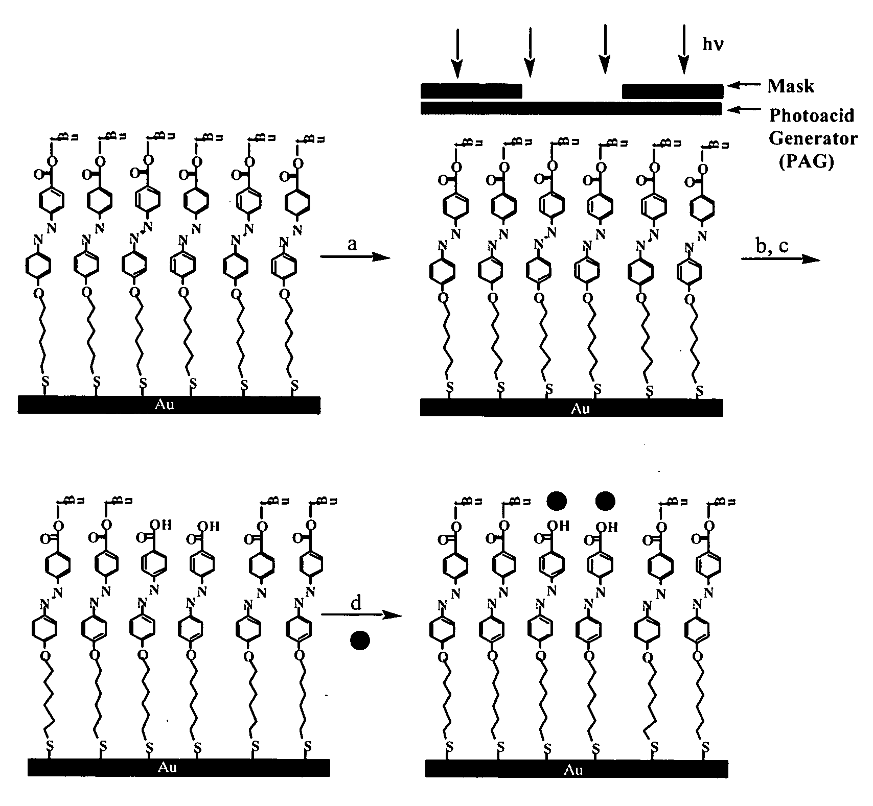
Self-Assembled Monolayers

Synthesis of 4-[4-(6-Mercapto-hexyloxy)-phenylazo]-benzoic acid t-butyl ester (Compound 1)

[0185] 4-[4-(6-Bromo-hexyloxy)-phenylazo]-benzoic acid t-butyl ester was synthesized following a reported procedure [Macromolecule, 1993, 26, 7103-05; J. Fluorine Chem., 1995, 74]. 4-Amino-benzoic acid t-butyl ester (Fluka, 4.81 g, 25 mmol) was dissolved in 55 mL of dilute hydrochloric acid aqueous solution. After cooling in an ice bath, the acid mixture was diazotized by adding drop-wise a solution of 1.73 g of NaNO2 in 5 mL of water at 0° C. to the acid mixture. The solution mixture turned a strong yellow. The solution was diluted with 100 mL of chilled methanol and coupling was carried out by slowly adding the diazotized solution to a chilled solution of phenol (2.34 g, 24 mmol), KOH (2.69 g, 48 mmol), and 25 mL of MeOH at 0° C. to form an orange-yellow precipitate. The solution was stirred for 2 hours in an ice water bath. The precipitate was filtered off, dried a...


PUM

PropertyMeasurementUnit
pressureaaaaaaaaaa
pressureaaaaaaaaaa
pressureaaaaaaaaaa

Abstract

The present invention is directed to methods for coating monolayer films of surface-active polymers onto substrates of arbitrary shape. The present invention also provides molecular-based methods and processes that can be used to control the chemical and physical nature of surfaces and interfaces. The present invention is directed to methods for modifying functional groups in a homogenous way and controlling the spatial distributions of surface functional groups. The invention is directed to methods for modifying a substrate having a surface comprising coating a macromolecular surfactant comprising a modifiable functional group onto the surface of the substrate, wherein the modifiable functional group assembles to the air-coating interface, thereby modifying the surface of the substrate; wherein if the substrate comprises a first polymer and the macromolecular surfactant comprises a second polymer having a modifiable functional group, then the group is not modifiable by an acid to functionally modify the surface of the substrate. The invention is directed to devices made by these methods.

Description

[0001] This application is a continuation of International Patent Application No. PCT / US2004 / 042363, filed Dec. 16, 2004, which claims the benefit of provisional application U.S. Ser. No. 60 / 530,809, filed Dec. 18, 2003, which are both hereby incorporated by reference into the subject application in their entireties.[0002] The government may have certain rights in the present invention pursuant to a grant from the U.S. Army Research Laboratory and the U.S. Army Research Office, Grant No. DAAD19-00-10104, and a grant from the Materials Research Science and Engineering Centers program of the National Science Foundation, Award No. DMR-0213574.[0003] Throughout this application, various publications are referenced. The disclosures of these publications in their entireties are hereby incorporated by reference into this application in order to more fully describe the state of the art as known to those skilled therein as of the date of the invention described and claimed herein. [0004] The...

Claims


Application Information

Patent Timeline
Patent Type & Authority Applications(United States)
IPC IPC(8): B05D5/00A61L27/34A61L29/08B05D1/18B05D1/32B05D3/06B05D3/10C03C17/32C08J7/043C08J7/056C08J7/12C08J7/18G03F7/004G03F7/039G03F7/16G03F7/26H05K3/38
CPCA61L27/34A61L29/085B05D1/185B05D1/32B05D3/067B05D3/107B05D2401/90B82Y30/00B82Y40/00C03C17/32C07K17/00C08J7/047C08J7/12C08J7/18D06M23/005G03F7/0048G03F7/0392G03F7/165G03F7/265H05K3/389C08J7/0427C08J7/043C08J7/056
Inventor KOBERSTEIN, JEFFREY T.WANG, PENGPAN, FENG
Owner THE TRUSTEES OF COLUMBIA UNIV IN THE CITY OF NEW YORK
Why Eureka
Try Eureka