Light emitting halogen-silicate photophosphor compositions and systems

Inactive Publication Date: 2007-06-28
ACOL TECH
View PDF20 Cites 17 Cited by
  • Summary
  • Abstract
  • Description
  • Claims
  • Application Information

AI Technical Summary

Benefits of technology

[0035] It is a further object to provide new phosphor color shi

Problems solved by technology

These deficiencies reduce the functionality possible with orthosilicate and therefore wide use is probably not to be expected.
While systems and inventions of the art are desig

Method used


Image

  • Light emitting halogen-silicate photophosphor compositions and systems
  • Light emitting halogen-silicate photophosphor compositions and systems
  • Light emitting halogen-silicate photophosphor compositions and systems

Examples


example 1

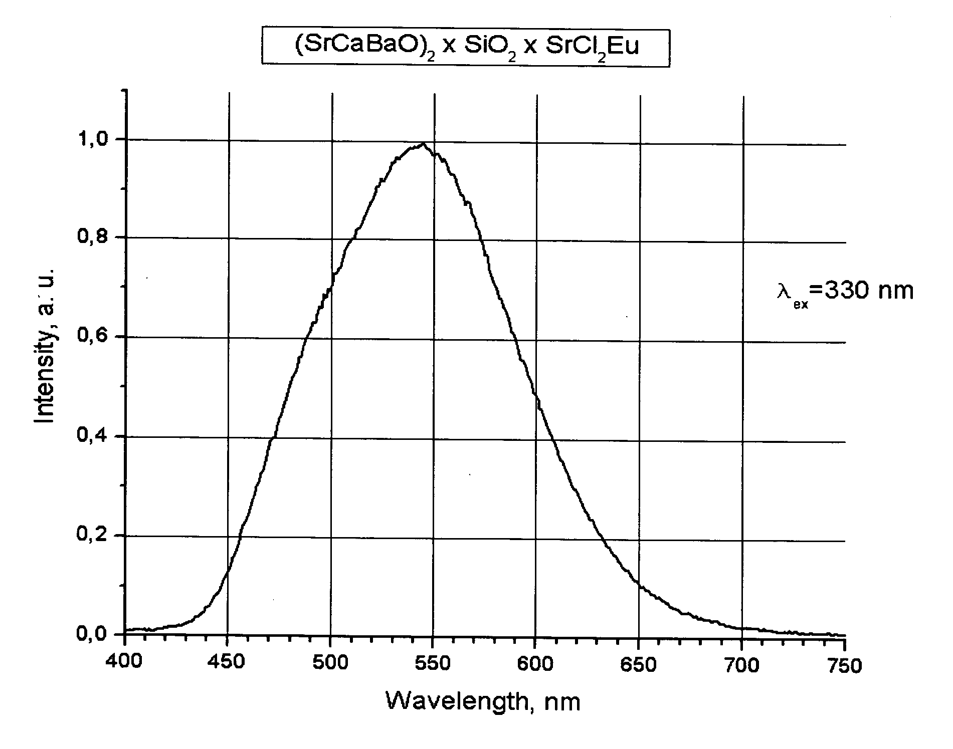
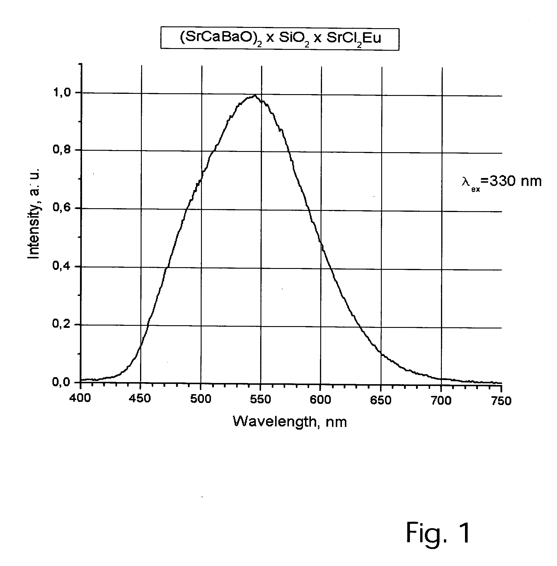
[0072] Mix 0.1M Sr(OH)28H2O; 0.05M SrF2; 0.05M SrCl2 with 0.005M europium nitrate (as 1% solution). Add 0.1M silica in the form of its highly dispersated technical trademark “Aerosil 100” into the mixture moistened by water. The mixture is dried at T=120° C. until dusting and is located at an alundum capsule with volume V=250 ml. The capsule is covered with a quartz cover and put to hydrogen conveyor oven in which the atmosphere is maintained with 5% H2 concentration (95% N2). The calcination of mixture is realized by means of gradual temperature elevating: T=240° for 1 hour, T=800° for 1 hour, T=1250° for 2 hours. The phosphor sample is cooled with oven cooling, at a rate of about 10° / minute. After cooled to 50° C., the resulting product is washed in a hot water bath with 1% NH4HF2 dissolved in it. The washed product Sr2SiO3(F,Cl)2 is dried at T=120° C. for 2 hours, sifted through the sieve with 50.0 micron apertures. Measuring of lighting parameters of the concrete sample 1-1 show...

example 2

[0073] 0.08M Sr(OH)2; 8H2O 0.02M Ba(OH)2; 8H2O; 0.002M Eu(NO3)3 (in the form of 0.1% solution) 0.05M SrF2; 0.05M SrCl2 are mixed in a parceline bowl V=400 ml. Into a wet mixture 0.1M fine-despersed silica “Aerosil-100” is added and dried until dusting at T=120° C. The mixture is put into alundum capsule V=500 ml, which is located to a hydrogen oven with bulk concentration of hydrogen [H2]=6%. The sample heating is made gradually, first at T=300° for 1 hour; then at T=900° C. for one additional hour and T=1280° C. for 2 hours. The capsule cooling is made together with the oven cooling with rate of 10° / minute. Thereafter, the sample is washed with a distillated water at T=50° C., dried and sifted through a sieve with 50.0 micron. Photophosphors of Table 2 having number 2-6 has the spectrum maximum position λ=527 with halfwidth λ0.5=85 nm. Photophosphor grains with a median diameter of d50=7.5 micron. Silicon organic phosphor suspension with its mass concentration 45% allows to make li...

example 3

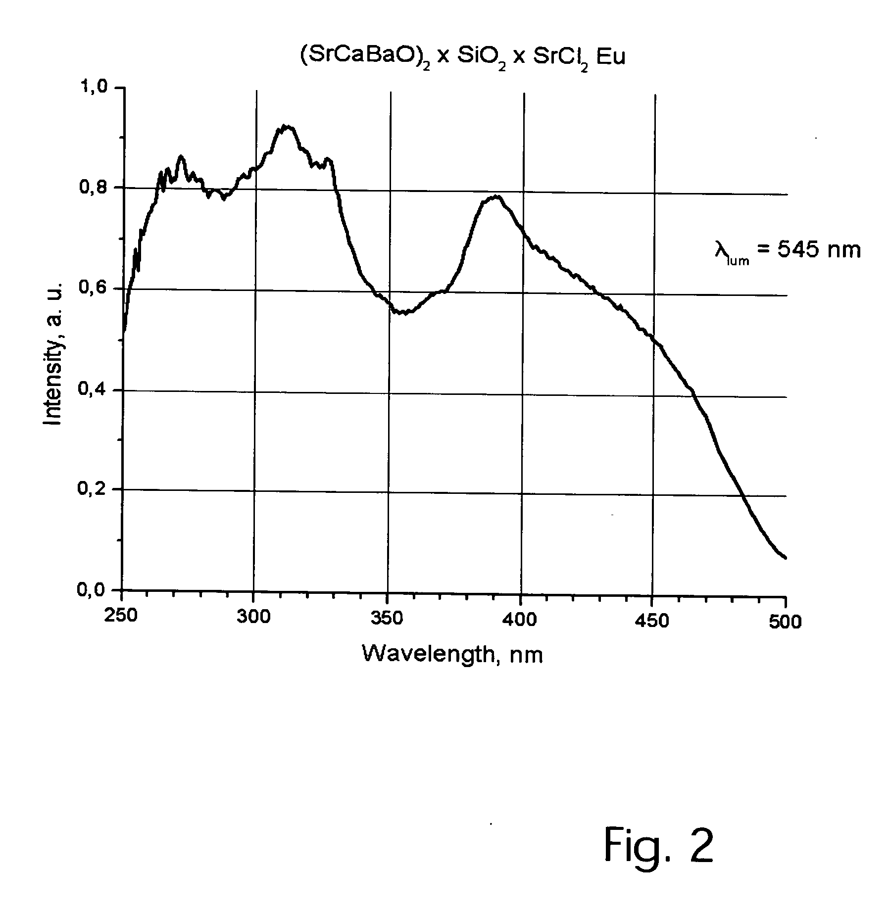
[0074] 0.2M Sr(OH)2; 8H2O 0.005M Eu(NO3)3 (solution 0.1%); 0.05M SrF2; 0.05M SrCl2 are mixed in alundum capsule with volume 250 ml. 0.1M SiO2 is added to a wet mixture, then mixed thoroughly and dried. The capsule is placed in a hydrogen oven of atmosphere: H2—2%; N2—98, which is gradually heated up to T=320° C. for 1 hour; T=820° C. for 1 hour; then T=1300° C. for 2 hours. The capsule is taken off at T=50° C., washed by a hot water, sifted through the sieve having 50.0 micron holes. The resulting photophosphor grains have a median diameter d50=4 micron, the average diameter, dav is about 6 micron. Phosphor color coordinates are x=0.40, y=0.44. In combination with silicon gel in proportion 30-70 (by mass) the phosphor provides white-rosy luminescence color together with a light-emitting device having a pump wavelength λ=460 nm.


PUM


Abstract

New high-performance, highly tunable photophosphors are presented. These photophosphor's pump spectra and emission spectra are both manipulated via variances in the formulation of compounds taught herein. In addition, new combinations of semiconductor devices in conjunction with these optically active materials are described. In particular, light emitting semiconductors fashioned as diodes from indium gallium nitride construction are combined with these photophosphors. High-energy short wavelength light mixes with the longer wavelengths light emitted by the halogen-silicate photophosphor to produce a broad spectrum perceived by human observers as “white light”.

Description

BACKGROUND OF THESE INVENTIONS [0001] 1. Field [0002] The following inventions disclosure is generally concerned with compositions having light emitting functionality and more specifically concerned with compostions arranged to provide a wavelength shifting function in for example light emitting diodes. [0003] 2. Prior Art [0004] For the first time the suggestion to incorporate Stoke's phosphor to the surface of indium-gallium light-emitting diode was recorded in the inventor certificate in favor of Abramov and others, numbered USSR No 697142. Considerable progress in physics of nitride light-emitting diodes, realized by S. Nakamura, “The blue laser diode”; chap 4. p 343-350; Springer-Verlag Berlin 1997; finally led to creating industrial “white” color light-emitting diodes. [0005] Shimizu presents similar invention in his U.S. Pat. No. 5,998,925, which we consider as an analogue. According to this patent, for semiconductor structures of InGaN, it is suggested using photophosphor ou...

Claims


Application Information

Patent Timeline
IPC IPC(8): H01J1/62
CPCC09K11/617C09K11/7706C09K11/7721C09K11/7734C09K11/7774Y02B20/181Y02B20/00C09K11/77342
Inventor ABRAMOV, VLADIMIR SEMENOVICHSOSCHIN, NAUM PETROVICHSHISHOV, ALEXANDER VALERIEVICHSCHERBAKOV, NIKOLAY VALENTINOVICH
Owner ACOL TECH
Why Eureka
Try Eureka