Cell structure for electrochemical devices and method of making same

a cell structure and electrochemical technology, applied in the direction of primary cell maintainance/servicing, sustainable manufacturing/processing, wound/folded electrode electrodes, etc., can solve the problems of internal power loss, shortening the useful life of li-ion cells, and often unsuitable older battery configurations to meet these increased demands

Inactive Publication Date: 2007-07-12
INVENTEX
View PDF15 Cites 44 Cited by
  • Summary
  • Abstract
  • Description
  • Claims
  • Application Information

AI Technical Summary

Problems solved by technology

Older battery configurations are often unsuitable to meet these increased demands.
Excessive temperature rise will destroy (e.g. melt the microporous polymer separator or autoignite the flammable organic electrolyte) or significantly shorten the useful life of the Li-ion cell.
Output values of existing electrochemical devices are typically small fractions of theoretically possible output values, because of internal resistances and other inefficiencies (hardware mass and volume).
The resistance to ion conduction between the electrode elements is one major source for internal power loss.
The ionic-impedance value, ρ, is not easily subject to modification and is not effective as a design parameter.
However, the very breadth of the facing electrodes and sandwiched electrolyte and separator raise another cause of concern, namely the structural sufficiency during assembly and during operation to maintain and support the electrode elements physically separated.
Current collectors used in these cell arrangements add significant weight, and thus reduced specific cell energy and power outputs.
Also, these cell arrangements provide electrodes of limited size and / or thickness, limiting the quantities of usable electrode materials and thus limiting maximum cell storage energy and / or operating cycle-life, particularly for rechargeable cells.
The dilemma of these designs is that power gains obtained by increasing the interfacial electrode area “A” across the electrolyte generally are typically offset by increased electrolyte thickness “1”, and the weight and volume of the current collectors reduce specific energy and power outputs.
Power can be increased, but only at the expense of reduced energy storage capacity per weight and volume and at increased costs due to needed additional hardware.
Existing bipolar cell arrangements do not escape this power and energy trade off dilemma; nor do fuel cell electrochemical devices.
These Li / organic-based electrolyte battery chemistries, although exhibiting quite high voltage (3-5 volts), have relatively low current density capabilities.
One limiting factor is the attempted use of relatively-thin components, i.e. the electrode and separator layers.
A further dilemma is the large number of small cells required to form such batteries.
A major power loss (internal heat generation) is the consequence of batteries with large numbers of small cells (e.g. 1 Ampere-hour (Ah) capacity as in the 18650 cell).
Nonetheless, this arrangement of substantially larger cells can still sacrifice 50% of the theoretical power of the cell chemistry.
However, previous button type cells, typically having very small capacity of 5-50 milli-Ah, lacked ease or consistency of battery assembly and / or distribution of high currents through the cell to the exterior terminals possibly due to the limited conductor paths of hardware components.
Rupture of a disc housing causes irreversible failure of that battery, and if a disc ruptures electrolyte may escape to further degrade the battery.
Under high pulse power, heat is generated at the electrode / separator interface due to limited ionic conduction.
Excessive temperature within the cell will locally shutdown the microporous polymer and higher temperatures result with further abuse.
Excessive abuse can lead to auto-ignition of organic electrolyte.

Method used


Image

  • Cell structure for electrochemical devices and method of making same
  • Cell structure for electrochemical devices and method of making same
  • Cell structure for electrochemical devices and method of making same

Examples


example 1

Lithium Battery Formed with Liquid Organic-Based Electrolyte

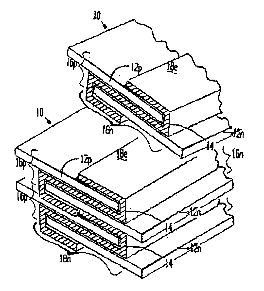
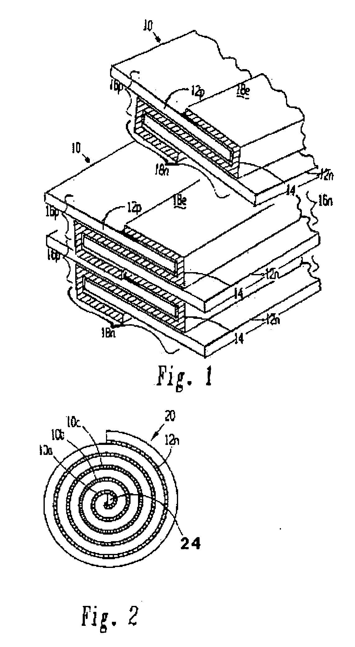
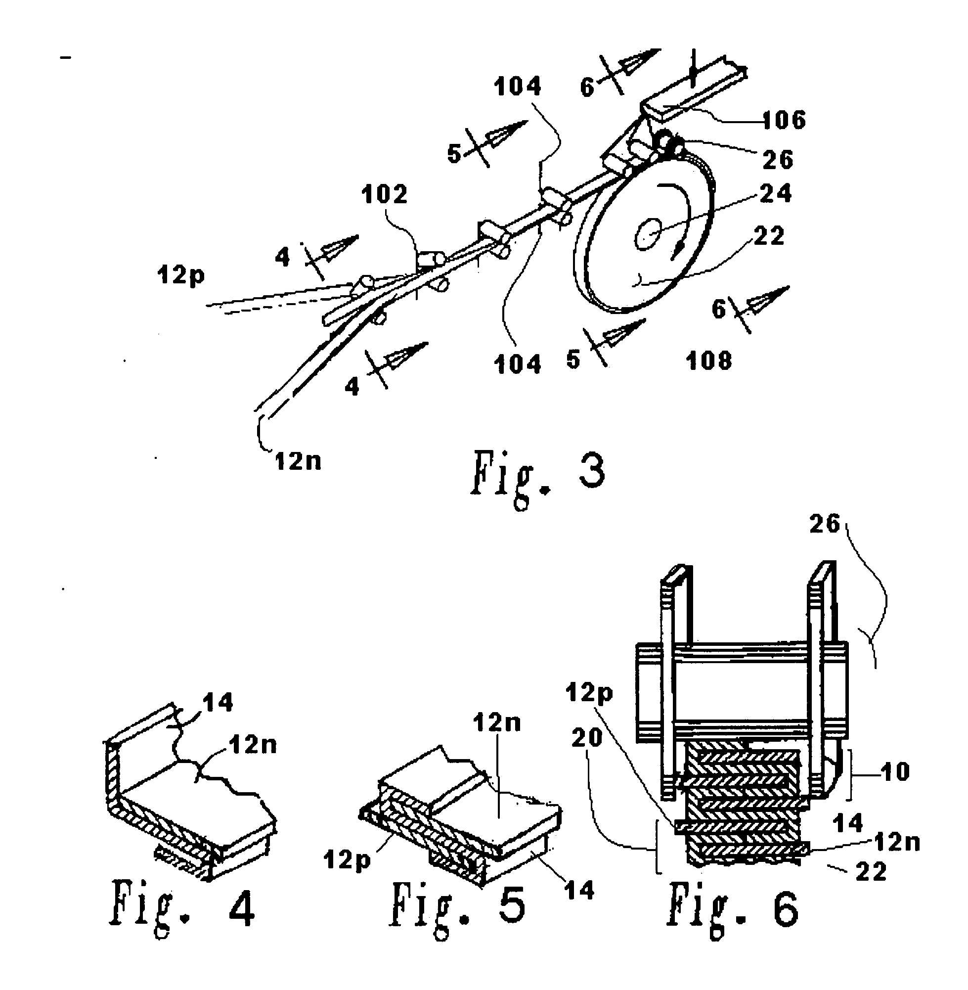
[0116] A lithium / organic electrolyte battery can be comprised or fabricated with a carbon / graphite anode; Lithiated nickel cobalt oxide (LiNiCoOx) with carbon cathode (electron conductor) and polyethylene / polypropylene microporous separator with ethylene carbonate / diethylene carbonate (EC / DEC) having dissolved LiPF6 salt as the electrolyte. A cell preassembly ribbon can be built by individual ribbons of the electrode / separator materials. Each electrode component ribbon is 0.060 mm thick and 6.5 mm wide, the separator is 0.025 mm thick and 6.0 mm wide making the overall dimensions 7.0 mm wide and 0.175 mm thick due to 0.5 mm extended electrode potion. Coiling the cell preassembly on itself approximately 350 times forms a 7.5 mm thick by 130 mm diameter electrode assembly disc. Two cup like subassemblies can be fitted around and edges of the electrode assembly and inserted into a peripheral gasket to join the two cups of the...

example 2

Lithium Battery with Liquid Electrolyte and Alternative Electrode Materials

[0119] A lithium / organic electrolyte battery can be comprised or fabricated as in Example 1. Li-ion cells are typically fabricated in an uncharged state with Lithiated metal oxide positive electrode and carbon black negative electrode. A Lithium salt, 1.2 M LiPF6, is dissolved in organic carbonates (e.g. EC:EMC 3:7 by weight, where EC:DEC is ethylene carbonate:ethylmethyl carbonate) from EM Science, USA. The cell is initially charged in which Li from the metal oxide positive forms LiC6 at the carbon negative. The cell has about 4.0 volts in its fully charged state. The cathode is selected from two major types of material: Lithium nickel-cobalt doped Oxide and Lithium Manganese Oxide Spinel. Both compositions are available from FMC Corp. Lithium Div. Gastonia, N.C. 28054 as Lectro Plus 600 and Lectro Plus 300, respectively. The composition Li Nix Coy Mz O2 is where Ni x is 0.62O4 is where 2 Li:Mn ratio is 1.0...

example 3

Lithium Battery with Polymer-Based Electrolyte

[0125] A lithium / polymer electrolyte battery can be comprised of LiAl / PEO30—LiN(CF3SO2)2 / V2O5 cell with nanocrystalline V2O5 and LiV3O8 using apolyethylene oxide based polymer (PEO) electrolyte / separator. The LiAl alloy composite anode contains 60% LiAl powder (46.0 atom % Li), 35% polymer electrolyte, and 5% of acetylene carbon black on a copper substrate. A vanadium cathode of similar weight portion has an aluminum substrate. The thickness of the electrode laminates can range between 10 to 30 μm by a casting method. The cell preassembly ribbon can be built up by individually and sequentially painting with stencil guides, etc. the components on the underlying cell preassembly while being coiled on a mandrel. Each component ribbon can be 0.05 mm thick; and each electrode can be 0.95 mm wide and the electrolyte can be 1.00 mm wide overall with the 0.05 mm wide double thick staggered end portions, to define a cell preassembly 1.00 mm wide...


PUM

PropertyMeasurementUnit
current densityaaaaaaaaaa
specific poweraaaaaaaaaa
diameteraaaaaaaaaa

Abstract

An electrochemical device comprising alternating layers of positive and negative electrodes separated from each other by separator layers. The electrode layers extend beyond the periphery of the separator layers providing superior contact between the electrodes and battery terminals, eliminating the need for welding the electrode to the terminal. Electrical resistance within the battery is decreased and thermal conductivity of the cell is increased allowing for superior heat removal from the battery and increased efficiency. Increased internal pressure within the battery can be alleviated without damaging or removing the battery from service while keeping the contents of the battery sealed off from the atmosphere by a pressure release system. Nonoperative cells within a battery assembly can also be removed from service by shorting the nonoperative cell thus decreasing battery life.

Description

[0001] This application claims priority to U.S. Provisional Patent Application No. 60 / 305,339, filed Jul. 13, 2001 and U.S. application Ser. No. 10 / 192,818, filed Jul. 10, 2002, the entire contents of which are hereby incorporated by reference.FIELD OF THE INVENTION [0002] The present invention relates to improved electrochemical devices, such as batteries, capacitors, fuel cells, sensors or the like. More specifically this invention relates to more user-friendly electrochemical devices that provide high specific power and energy outputs per weight and volume of the device, and to the methods of making these improved electrochemical devices. BACKGROUND OF THE INVENTION [0003] With the increasing pace of advances in electronics there has been a corresponding increase in the need for electrochemical devices that provide the energy density, efficiency and safety to power advanced electronic devices, especially portable electronic devices, while still being economically viable. Older ba...

Claims


Application Information

Patent Timeline
Patent Type & Authority Applications(United States)
IPC IPC(8): H01M2/18H01M2/08H01M2/12H01M6/10H01M6/50H01M10/04H01M10/42H01M10/50H01M50/449H01M50/469
CPCH01M2/0227Y02T10/7011H01M2/1229H01M2/164H01M2/1686H01M2/18H01M6/10H01M6/5038H01M10/04H01M10/0413H01M10/0431H01M10/045H01M10/0525H01M10/0583H01M10/0587H01M10/345H01M10/4207H01M10/5004H01M10/5016H01M10/503H01M10/5042H01M10/5057H01M10/5059H01M10/5075H01M2/0413H01M10/625H01M10/654H01M10/6556H01M10/6557H01M10/6567H01M10/643H01M10/613Y02E60/10H01M50/56H01M50/171H01M50/325H01M50/449Y02P70/50H01M50/469
Inventor KAUN, THOMAS D.
Owner INVENTEX
Why Eureka
Try Eureka