Carbon-based electrically conducting filler, composition and use thereof
a technology of electrical conductivity and filler, which is applied in the direction of conductors, non-metal conductors, mechanical devices, etc., can solve the problems of difficult difficult to disclose, and so as to achieve stable conductivity and less deterioration of physical properties. , the effect of high conductivity
Inactive Publication Date: 2007-08-09
SHOWA DENKO KK
View PDF15 Cites 25 Cited by
- Summary
- Abstract
- Description
- Claims
- Application Information
AI Technical Summary
Benefits of technology
[0019] In view of the foregoing, an object of the present invention is to form a stable conductive network through addition of a very small amount of a conductive filler, and more specifically, to provide a conductive plastic in which a conductive filler is dispersed in a polymer; inter alia, a plastic product which contains a conductive filler in an amount equivalent to the conventional amount and yet exhibits higher conductivity or a plastic product which contains a smaller amount of a conductive filler and yet exhibits conductivity equivalent to or higher than the conventionally attained conductivity, and a composition which exhibits stable conductivity and less deterioration in physical properties during any molding methods.
[0020] Another object of the present invention is to provide a composite material composition which enables production of a molded product with low warpage, which exhibits isotropy in mechanical properties, which exhibits excellent dynamic properties (e.g., strength and elastic modulus), electrical conductivity, thermal conductivity, sliding characteristics and surface smoothness, and which exhibits excellent cycle performance during the course of injection molding.
[0021] Still another object of the present invention is to provide a sliding member composition and a production method thereof, which composition exhibits durability under high temperature and heavy load; has a low friction coefficient (high wear resistance); rapidly releases generated heat by virtue of high thermal conductivity; inflicts no damage on the counter member even when the counter member is made of aluminum; and maintains its performance for a long period of time.
Problems solved by technology
Thus, when such carbon materials are employed, stable conductivity is very difficult to attain.
However, the publication claims a considerably wide scope of resin composition, and some examples are unreproducible, leaving questions of credibility to the disclosure.
However, a resin composite material employing PAN-based CF or pitch-based CF involves problems that the filler tends to be oriented in the direction of flow of the resin during the injection molding of the composite material, and therefore molding shrinkage and mechanical properties in the flow direction tend to differ from those in the direction perpendicular to the flow direction.
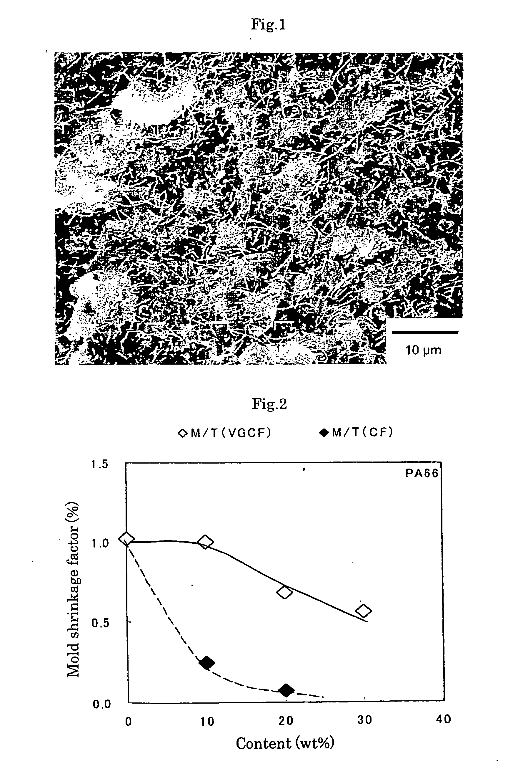
In addition, such a resin composite material poses problems that anisotropy in alignment of the filler causes warpage of a product produced by molding the resin composite material (see FIG. 2), or causes unsatisfactory dimensional accuracy of the molded product.
Particularly, in precision molded parts requiring high dimensional accuracy, anisotropy in alignment of a filler employed in the resin is detrimental.
However, needless to say, such whiskers fail to impart satisfactory electrical conductivity to resin.
Furthermore, the resultant composite material fails to exhibit satisfactory physical properties and sufficient isotropy in physical properties, although the isotropy is improved as compared with the case of a composite material employing PAN-based CF and the like.
When electrically conductive carbon black is employed as a filler in a composite material, the resultant composite material exhibits relatively good isotropy in electrical conductivity and mechanical properties (e.g., bending strength), but the composite material is totally unsatisfactory in reinforcing mechanical properties.
However, the composite material exhibits a thermal conductivity of 1 W / mK or less, and thus high cycle molding cannot be performed at a high mold temperature.
Therefore, the composite material containing high-aspect-ratio carbon fiber exhibits low thermal conductivity, and cycle performance of the composite material is deteriorated when a high-temperature mold is employed.
Currently, a composite material employing vapor grown carbon fiber having a high aspect ratio fails to achieve satisfactory results.
Though a plastic material has self-lubricating property that is required for a sliding member, it exhibits a low PV limit value and low thermal conductivity as compared with a metallic material,.
Therefore, heat accumulation in the plastic material cannot be prevented, resulting in poor mechanical properties (e.g., rigidity) .
A composite material containing such carbon fiber exhibits excellent dynamic properties and heat resistance, but has unsatisfactory wear resistance.
Therefore, when such a composite material is employed as a sliding member for a variety of industrial purposes, the sliding member has a shortened service life, and has not always achieved the desired results in practical use.
A carbon-fiber-containing composite sliding member causes damage not only to a soft aluminum material but also to hard steel.
Thus, such carbon fiber is not suitable for use in a sliding member.
However, in this sliding member, merely wear resistance is improved, and load resistance and heat resistance, which are required for the aforementioned sliding member, are insufficiently improved.
However, since this sliding member contains a synthetic resin, the member is not suitable for use at high temperature, in the presence of a corrosive fluid, or under application of high load.
In addition, since this sliding member contains molybdenum disulfide, oxidation of molybdenum may occur under oxygen-rich conditions, leading to an increase in the friction coefficient of the member.
However, similar to the case of the above-described sliding member, limitations are imposed on the use of this sliding member.
Although this sliding member exhibits satisfactory performance, the sliding member involves problems in terms of, for example, cost, since the member employs expensive carbon nanotube and requires a very cumbersome production process.
Method used
View moreImage
Smart ImageViewing Examples
Examples
examples
[0146] The present invention will next be described in more detail by way of examples, which should not be construed as limiting the invention thereto. [0147] (1) An electrically conductive filler and composition thereof:
Login to View More PUM
| Property | Measurement | Unit |
|---|---|---|
| Temperature | aaaaa | aaaaa |
| Temperature | aaaaa | aaaaa |
| Temperature | aaaaa | aaaaa |
Abstract
A conductive composition comprising a vapor grown carbon fiber having an aspect ratio of 40 to 1,000, preferably 65 to 1,000, and a specific surface area or fiber diameter of the fiber within a predetermined range, and a preferable peak intensity ratio (I0=I1360 / I1580) of 0.1 to 1, wherein I1580 represents a peak height at 1,580 cm−1 and I1360 represents a peak height at 1,360 cm−1 in a Raman scattering spectrum; and a resin composition containing the composition; and a production method thereof. The present invention provides: i) a composition which exhibits stable conductivity and less deterioration in physical properties during any molding methods in a conductive plastic in which a conductive filler is dispersed in a polymer; ii) a composite material composition for precision molding which enables production of a molded product with low warpage and is excellent in mechanical properties and performance during the injection molding; and iii) a sliding member composition which exhibits durability under high temperature and heavy load and has a low friction coefficient.
Description
CROSS REFERENCE TO THE RELATED APPLICATIONS [0001] This is an application filed pursuant to 35 U.S.C. Section 111(a) with claiming the benefit of U.S. Provisional application Ser. No. 60 / 564,969 filed Apr. 26, 2004, U.S. Pat. No. 60 / 564,972 filed Apr. 26, 2004, U.S. Pat. No. 60 / 564,974 filed Apr. 26, 2004 and U.S. Pat. No. 60 / 605,508 filed Aug. 31, 2004 under the provision of 35 U.S.C. Section 111(b), pursuant to 35 U.S.C. Section 119(e) (1).TECHNICAL FIELD [0002] The present invention relates to a carbon-based conductive filler, a composition and use thereof. More particularly, the invention relates to a carbon-based conductive filler which can easily be dispersed in a matrix resin, thereby readily forming a conductive network in the resin, a conductive composition containing the filler and use thereof. BACKGROUND ART [0003] Conventionally, properties such as conductivity and antistatic characteristics have long been imparted to a thermoplastic resin, which is an electrically insul...
Claims
Login to View More Application Information
Patent Timeline
 IPC IPC(8): H01B1/12C08J5/04C08K7/06C08L101/00H01B1/00H01B1/24H01B5/16
CPCC08J3/201C08J5/042H01B1/24C08K7/06F16C33/201C08J2377/00C08K2201/016
Inventor NAGAO, YUJIYAMAMOTO, RYUJI
Owner SHOWA DENKO KK
Features
- R&D
- Intellectual Property
- Life Sciences
- Materials
- Tech Scout
- Unparalleled Data Quality
- Higher Quality Content
- 60% Fewer Hallucinations
Learn More Browse by: Latest US Patents, China's latest patents, Technical Efficacy Thesaurus, Application Domain, Technology Topic, Popular Technical Reports.
© 2025 PatSnap. All rights reserved.Legal|Privacy policy|Modern Slavery Act Transparency Statement|Sitemap|About US| Contact US: help@patsnap.com


