Optical recording method, optical recording apparatus and optical recording medium

a recording method and optical recording technology, applied in the field of optical recording methods for recording information, can solve the problems of generating diffraction noise upon information reproduction, troublesome to distinguish data recorded in the data area over data recorded as synchronization marks, and undesired reduction of recording sensitivities of areas near specific positions, etc., to achieve high-speed digital data processing, less noise occurrence upon information reproduction, and the effect of high-multiplexing recording

Inactive Publication Date: 2007-09-27
FUJIFILM CORP
View PDF5 Cites 14 Cited by
  • Summary
  • Abstract
  • Description
  • Claims
  • Application Information

AI Technical Summary

Benefits of technology

[0018]It is an object of the present invention to solve the foregoing problems in the art and to achieve the object described below. That is, an object of the present invention is to provide an optical recording method, an optical recording apparatus and an optical recording medium that are capable of high-multiplexing recording and of recording with less noise occurrence upon reproduction of information and that excel in high-speed digital data processing.

Problems solved by technology

When the light intensity increases at specific positions, it results in consumption of a large amount of such photosensitive materials as a photoinitiator and / or monomers in the recording layer at positions corresponding to those specific positions, and thus the recording sensitivities of areas near the specific positions undesirably decrease.
Moreover, when shift-multiplex recording is performed, cycles of this site-specific high-light intensity recording are repeated, leading to generation of diffraction noise upon information reproduction.
Thus, it is troublesome to distinguish data recorded in the data area over data recorded as synchronization marks.
For this reason, the tracking element pattern cannot achieve high-speed data processing.

Method used


Image

  • Optical recording method, optical recording apparatus and optical recording medium
  • Optical recording method, optical recording apparatus and optical recording medium
  • Optical recording method, optical recording apparatus and optical recording medium

Examples


example 1

[0296]The optical recording medium of Example 1 was prepared in the following way by depositing, in order, a recording layer, a second gap layer, a filter layer, a first gap layer, and a second substrate on a first substrate. The filter layer was formed by preparing a film-shaped filter and depositing it on the second gap layer.

—Components in Photosensitive Composition Solution for Recording Layer—

[0297]A photosensitive composition made of the following components was stirred in a nitrogen flow to prepare a photosensitive composition solution.

Biscyclohexylmethane diisocyanate31.5 PartsPolypropyleneoxide triol (molecular weight = 1,000)61.2 PartsTetramethyleneglycol 2.5 Parts2,4,6-Tribromophenyl acrylate 3.1 PartsPhotoinitiator0.69 Parts(IRGA CURE 784, produced by Ciba Specialty Chemicals)Dibutyl tin dilaurate1.01 Parts

Preparation of Filter

[0298]Initially, polyvinyl alcohol (bland name: MP 203, produced by Kuraray Co., Ltd.) was applied on a polycarbonate film of 100 μm thickness (bl...

examples 2 to 5

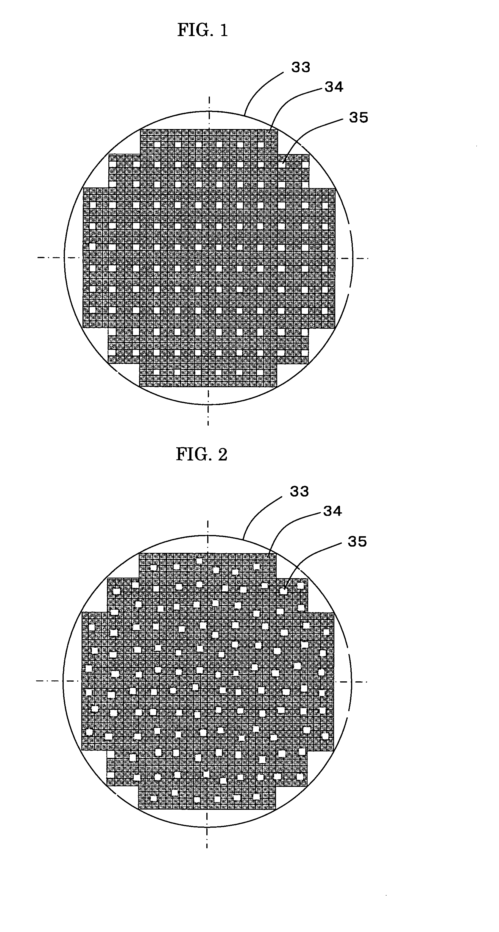
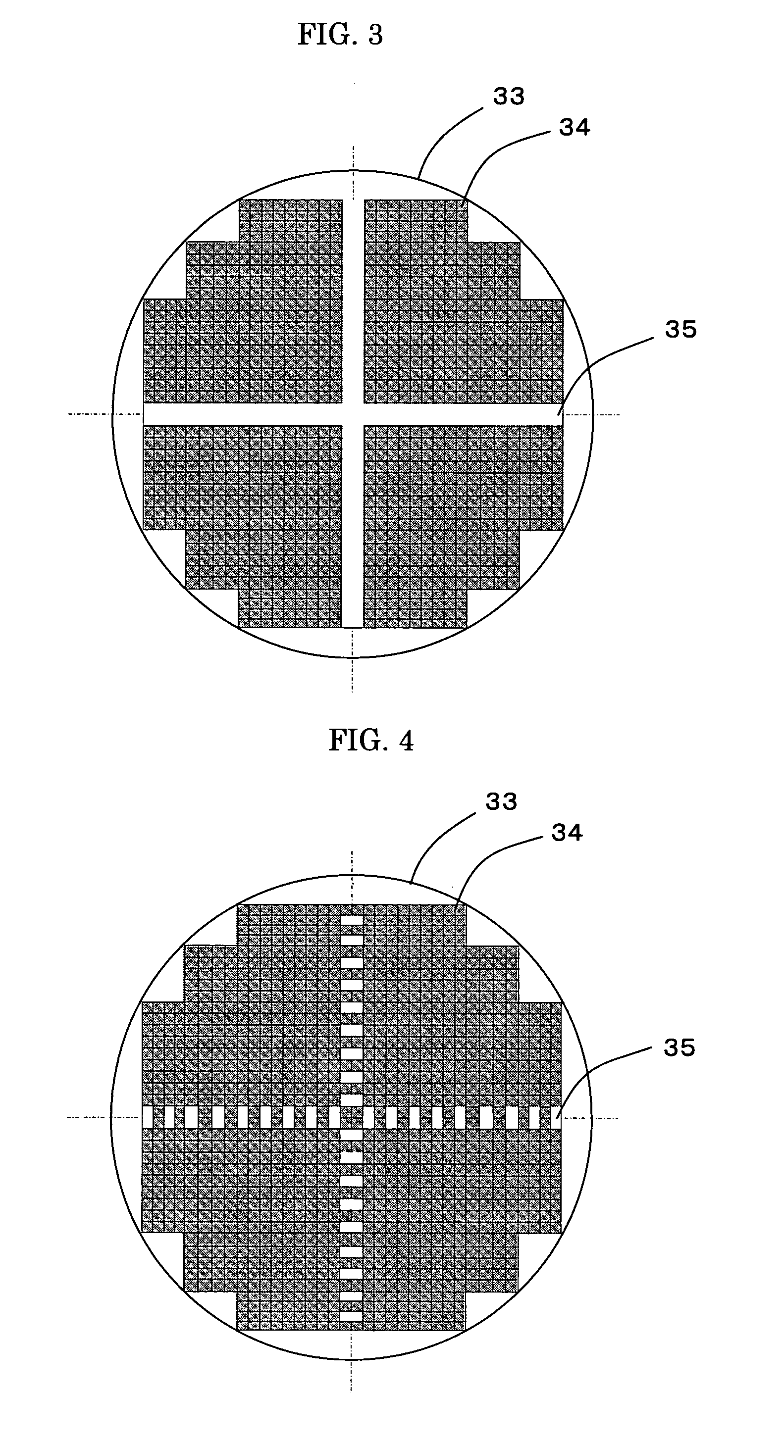
[0321]As in Example 1, 50-fold multiplexing recording and single-hologram recording were conducted on optical recording media prepared in the same manner as those of Example 1, with synchronization marks arranged in different patterns given in Table 2, followed by measurement of the SNR values for each recording medium as in Example 1. The measurement results are given in Table 2.


PUM

PropertyMeasurementUnit
wavelengthsaaaaaaaaaa
wavelengthaaaaaaaaaa

Abstract

To provide an optical recording method including: applying information and reference beams onto an optical recording medium to record information therein, the optical recording medium having a recording layer for recording the information by holography, wherein at least the information beam is passed through a spatial light modulator and is formed as a two-dimensional pattern composed of a data area and a plurality of synchronization marks for detecting information concerning the positions of data recorded in the data area, and wherein the synchronization marks are arranged in a random pattern so that in a Fourier-transformed image of the two-dimensional pattern, light intensities derived from the synchronization marks are lower than light intensities in a Fourier-transformed image of a two-dimensional pattern composed of a data area and a plurality of synchronization marks arranged in a grid pattern, the light intensities being derived from the synchronization marks arranged in a grid pattern.

Description

BACKGROUND OF THE INVENTION[0001]1. Field of the Invention[0002]The present invention relates to an optical recording method for recording information by holography, an optical recording apparatus and an optical recording medium. More specifically, the present invention relates to an optical recording method, an optical recording apparatus and an optical recording medium that are capable of high-multiplexing recording and of recording with less noise occurrence upon reproduction of information and that excel in high-speed digital data processing.[0003]2. Description of the Related Art[0004]An example of a proposed optical recording medium utilizing holography is an optical recording medium 20 shown in FIG. 10, wherein servo pit patterns 3 are formed over a surface of a second substrate 1, a reflective layer 2 made of aluminum or the like is formed on the servo pit patterns 3, a recording layer 4a is formed on the reflective layer 2, and a first substrate 5 is formed on the recording...

Claims


Application Information

Patent Timeline
Patent Type & Authority Applications(United States)
IPC IPC(8): G11B7/00
CPCG03H1/16G11B2220/2504G11B7/00781G11B7/24044G11B7/2405G11B7/245G11B7/246G11B7/2463G11B7/252G11B7/2585G11B7/26G11B20/1217G11B27/10G11B27/3027G11B2020/1287G11B7/0065
Inventor SASAKI, TOSHIO
Owner FUJIFILM CORP
Why Eureka
Try Eureka