
Method, system and apparatus for dermatological treatment and fractional skin resurfacing

Inactive Publication Date: 2007-10-11
THE GENERAL HOSPITAL CORP
View PDF6 Cites 24 Cited by
  • Summary
  • Abstract
  • Description
  • Claims
  • Application Information

AI Technical Summary

Benefits of technology

[0020] It is therefore one of the objects of the present invention to provide a system, process and apparatus which combine safe and effective treatment to improve dermatological disorders with fewer side effects. Another object of the present invention is to provide a system, process and apparatus which cause a smaller amount of damage to the epidermis while inducing a greater degree of well-controlled thermal damage below the skin surface.
[0024] A vacuum arrangement can be provided which is configured to pull the portion of the skin surface containing the target location closer to the optical arrangement. This can stretch the skin in the vicinity of the target location, which may allow more accurate positioning of the radiation with respect to the skin. The vacuum arrangement may also promote more rapid healing of the damaged area, especially near or at the target area, by providing relative compression of the area after the vacuum is released and the skin is no longer being stretched.

Problems solved by technology

Certain treatments which use electromagnetic radiation have been used to improve skin defects by inducing a thermal injury to the skin, which results in a complex wound healing response of the skin.
LSR treatments can result in thermal damage and / or ablative removal of the upper skin surface of the area being treated, including the epidermis and optionally portions of the upper dermis.
The LSR treatment with pulsed CO2 lasers can be particularly aggressive, likely causing a thermal skin damage to the epidermis and at least to the superficial dermis.
Following the LSR treatment using CO2 lasers, a high incidence of complications can occur, including persistent erythema, hyperpigmentation, hypopigmentation, scarring, and infection (e.g., infection with Herpes simplex virus).
Using the Er:YAG laser can result in a thinner zone of thermal injury within the residual tissue of the target area of the skin.
However, LSR that uses the Er:YAG laser may produce side effects similar to those made by the LSR procedure that uses the CO2 laser within the first days after the treatment.
Patients may experience major drawbacks after each LSR treatment, including edema, oozing, and burning discomfort during, e.g., first fourteen (14) days after treatment.
These drawbacks can be unacceptable for many patients.
A further problem with the LSR procedures may be that the procedures are relatively painful, and therefore may generally require an application of a significant amount of analgesia.
One of the limitations of the LSR procedures that use CO2 or Er:YAG lasers is that ablative laser resurfacing generally may not be effectively performed on the patients with dark complexions.
For example, the removal of a pigmented epidermis tissue can cause a severe cosmetic disfigurement to patients with a dark complexion.
Such problem may last from several weeks up to years, which is considered by some patients and physicians to be unacceptable.
Another limitation of the LSR procedures is that ablative resurfacing in areas other than the face generally have a greater risk of scarring.
The LSR procedures in areas other than the face result in an increased incidence of an unacceptable scar formation because the recovery from skin injury within these areas may not be very effective.
This type of wound healing can result in a decrease of photoaging related structural damage.
While that these techniques can assist in avoiding epidermal damage, one of the drawbacks of such techniques is their limited efficacies.
Even after multiple treatments, the clinical improvement is often far below the patient's expectations.
In addition, a clinical improvement is usually several months delayed after a series of treatment procedures.
Another limitation of the NCR procedures relates to the breadth of acceptable treatment parameters for safe and effective treatment of dermatological disorders.
The NCR procedures generally rely on an optimum coordination of laser energy and cooling parameters, which can result in an unwanted temperature profile within the skin leading to either no therapeutic effect or scar formation due to the overheating of a relatively large volume of the tissue.
Yet another disadvantage of the non-ablative procedures relates to the sparing of the epidermis.
A further disadvantage of both ablative and nonablative resurfacing is that the role of keratinocytes in the wound healing response is not capitalized upon.
Still another drawback with all LSR and NCR techniques now used is the appearance of visible spots and / or edges after treatment due to inflammation, pigmentation, or texture changes, corresponding to the sites of treatment.
This procedure differs from the traditional resurfacing procedures, in that the entirety of the target area (or at least most of it) is damaged.
However, conventional FS techniques are limited in the amount of thermal damage or ablation that can be created below the epidermis by the need to avoid ablating or damaging too much of the epidermal tissue.

Method used


Image

  • Method, system and apparatus for dermatological treatment and fractional skin resurfacing
  • Method, system and apparatus for dermatological treatment and fractional skin resurfacing
  • Method, system and apparatus for dermatological treatment and fractional skin resurfacing

Examples


Embodiment Construction

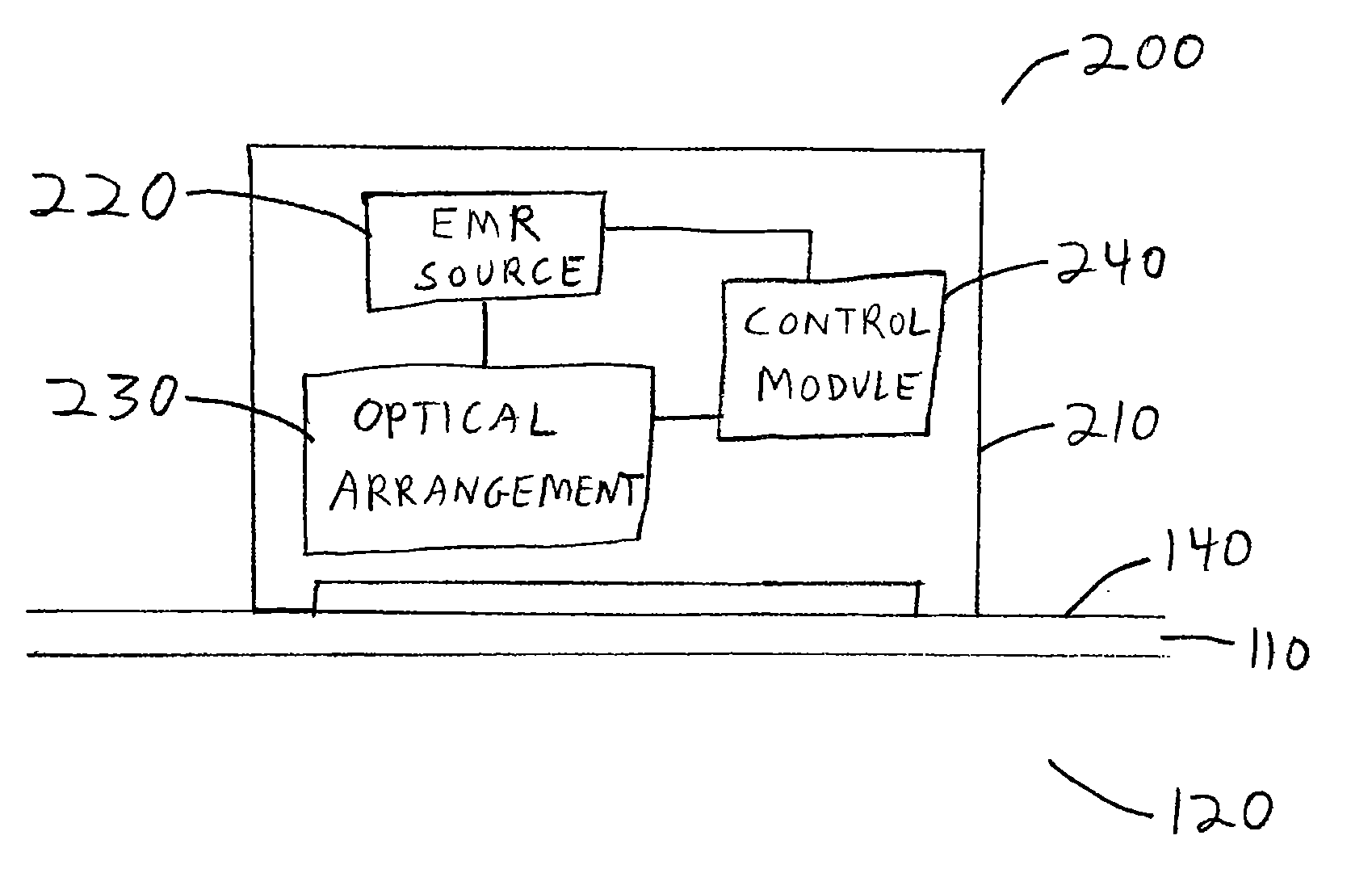
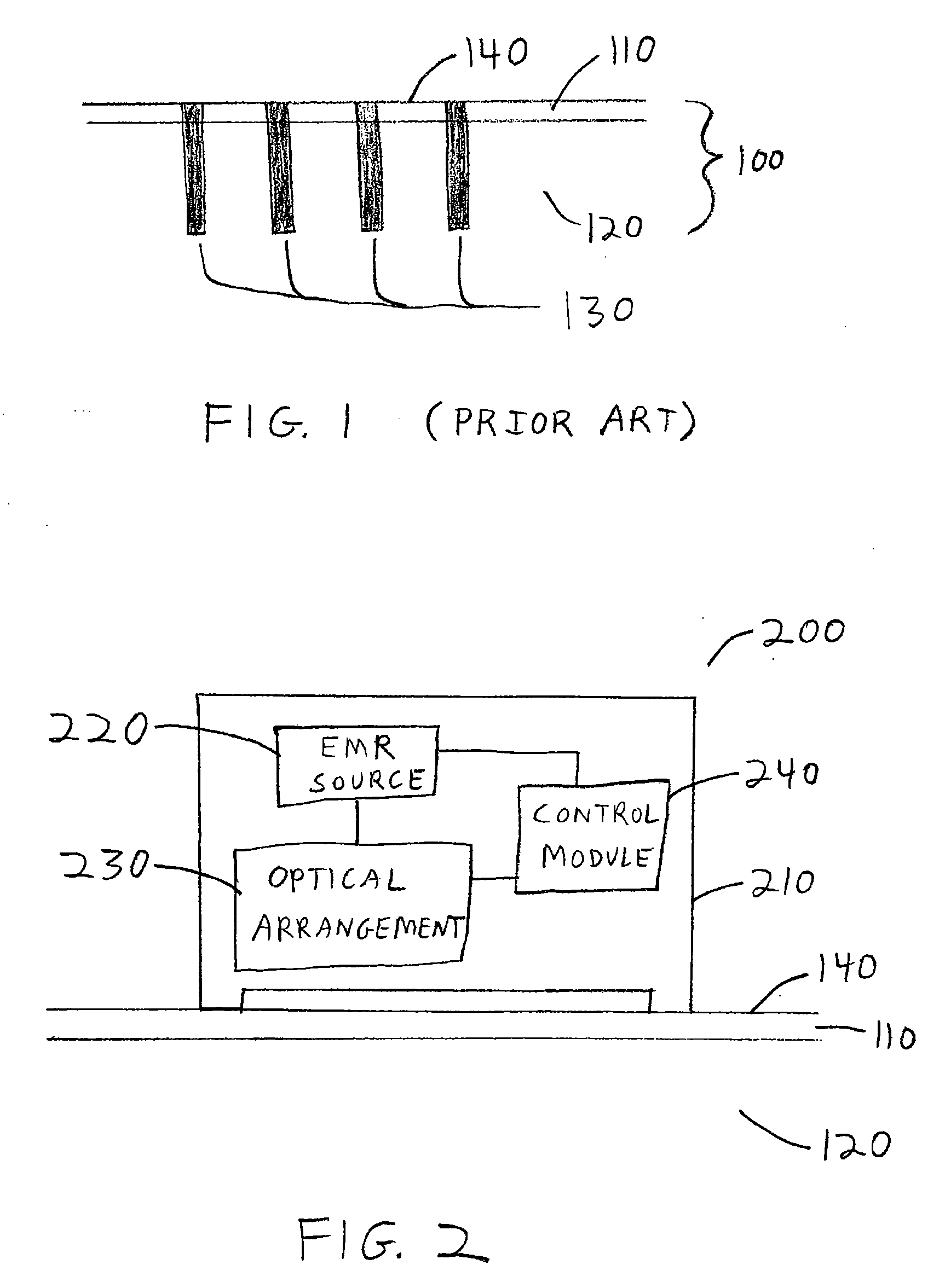
[0041]FIG. 1 shows a cross-sectional illustration of exemplary damage patterns produced by conventional fractional resurfacing of a target area of skin. An area of skin 100 includes an upper epidermis layer 110, and a lower dermis layer 120. A number of regions of thermal damage 130 extend from the surface of the skin 140 through the epidermis 110 and into the dermis 120.

[0042] These regions of thermal damage 130 can include tissue that has been heated sufficiently to cause at least some degree of tissue damage and / or cell death. The thermal damage can be produced by exposing the skin to a number of collimated beams generated by a source of electromagnetic radiation (“EMR”). These beams can be generated, e.g., by lasers, diodes, diode arrays, etc. Optionally, a portion of the regions of thermal damage 130 can include locations where the tissue has been ablated. Such ablation can be achieved, for example, by the use of highly-absorbed and / or high-powered EMR sources such as, e.g., C...


PUM


Abstract

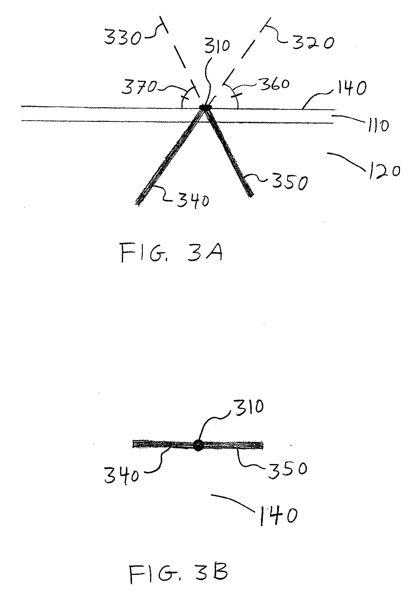
A system, method and apparatus are provided for treating dermatological conditions by generating a relatively large amount of thermal damage beneath a skin surface while generating relatively little thermal damage to the skin surface and / or epidermis. For example, the exemplary system, method and apparatus provide for directing a radiation beam onto a target location on the skin surface to thermally damage a volume of tissue beneath the target location, and directing a second radiation beam onto the same target location to thermally damage a different volume of tissue beneath the target location. The radiation beams may include ablative and / or non-ablative laser beams, or they may be generated by, e.g., a flashlamp, a tungsten lamp, a diode, or a diode array. The two beams may be pulsed. Further, they can be part of a single continuous wave beam, which can be rotated around an axis which passes through the target area, or which can be directed at a plurality of angles with respect to the skin surface.

Description

CROSS-REFERENCE TO RELATED APPLICATION [0001] This application is based upon and claims the benefit of priority from U.S. Patent Application Ser. No. 60 / 790,171, filed Apr. 7, 2006, the entire disclosure of which is incorporated herein by reference.FIELD OF THE INVENTION [0002] The present invention relates to methods and apparatus that use electromagnetic radiation for dermatological treatment and, more particularly to methods, systems and apparatus that use optical radiation to ablate or thermally damage target sites of skin tissue below the skin surface for dermatological treatment while ablating or damaging a relatively small area of the epidermis. BACKGROUND INFORMATION [0003] There is an increasing demand for repair of or improvement to skin defects, which can be induced by aging, sun exposure, dermatological diseases, traumatic effects, and the like. Certain treatments which use electromagnetic radiation have been used to improve skin defects by inducing a thermal injury to t...

Claims


Application Information

Patent Timeline
IPC IPC(8): A61B18/18
CPCA61B18/203A61B2018/00452A61B2018/00458A61B2018/208A61B2018/1807A61B2018/207A61B2018/0047
Inventor MANSTEIN, DIETERANDERSON, R. ROXLAUBACH, HANS-JOACHIMWALL, TOMI L.
Owner THE GENERAL HOSPITAL CORP
Learn More