High Power Vcsels With Transverse Mode Control

a transverse mode control and high-power technology, applied in the direction of semiconductor lasers, laser details, electrical apparatus, etc., can solve the problems of complex transverse modal behavior of vcsels at high pump rates, high optical power, and many inadequacies of vcsels

Inactive Publication Date: 2007-10-18
ARIZONA STATE UNIVERSITY
View PDF12 Cites 230 Cited by
  • Summary
  • Abstract
  • Description
  • Claims
  • Application Information

AI Technical Summary

Benefits of technology

[0018] Objects of the invention, then, are, as compared to the prior art, simpler device design and growth, simpler device processing, better yield, lower cost and better performance of the laser.
[0020] a. Multiple oxide apertures to provide controlled spatial carrier distribution;

Problems solved by technology

However, high fiber-coupling efficiencies are only reached at low optical powers, because with increasing output power higher order transverse modes are supported by the cavity.
In general, the complex transverse modal behavior of VCSELs at high pump rates is a major drawback for many practical applications.
Despite many of their inherent advantages over their rivals, VCSELs still suffer from many inadequacies.
Most prominent are “limited power” and lack of “modal purity.” These unresolved issues have compelled the VCSEL to enjoy only a 10% share of the whole semiconductor laser market.
This approach involves a risk of degrading the active layer and increasing free carrier absorption, so the power output is limited.
This approach suffers from low speed of the device as the cavity length is very long.
This approach involves complex processing steps which adds to the cost, limits the active size of the device and eventually limits the output single-mode power.

Method used


Image

  • High Power Vcsels With Transverse Mode Control
  • High Power Vcsels With Transverse Mode Control
  • High Power Vcsels With Transverse Mode Control

Examples


Embodiment Construction

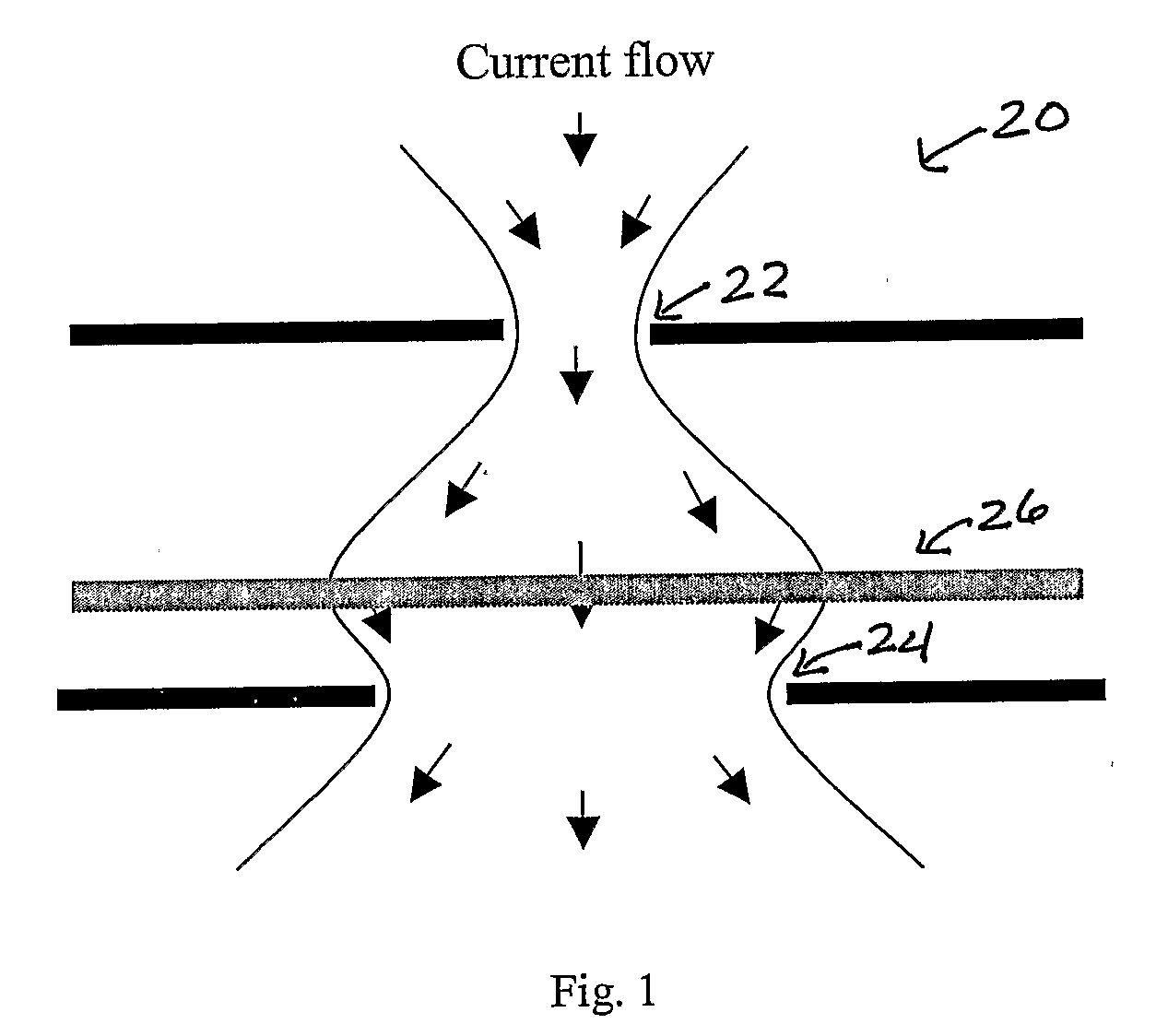
[0043] A schematic diagram of the location of a pair of apertures in accordance with the invention is shown in FIG. 1. In a VCSEL construction 20, at least two oxide apertures 22 and 24 with different sizes are located on each side of an active region 26 at varying distances from the active region in the DBRs or mirror stacks on each side of the active region. Current confinement and spreading in the cavity is controlled by the size and position of the oxide apertures. The current distribution strongly favors single mode operation if the size and distance of the apertures from the active region are optimally chosen. Since the mirror stacks are built up in pairs of mirrors as is known in DBR creation, distances of the oxide layers and oxide apertures from the active region are measured here and referred to here in “mirror pairs.”

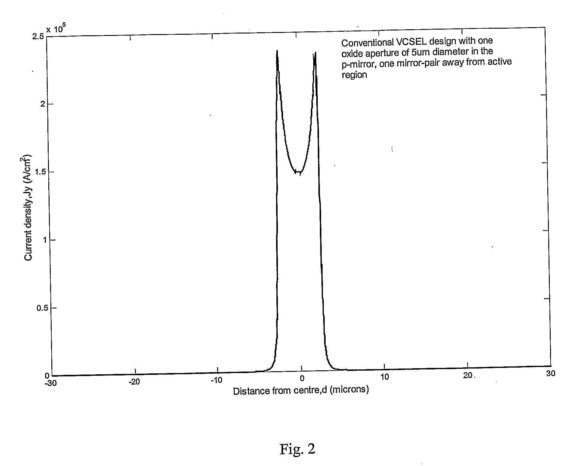
[0044] Detailed 3D modeling was carried out using Femlab, a popular finite element tool, to see the effect of double oxide-aperture in profiling the spatial ...


PUM


Abstract

A single mode high power laser device such as a VCSEL is formed with two oxide apertures, one on each side of the active region or cavity. The sizes of the apertures and the distances from the apertures to the cavity center are chosen or optimum, near-Gaussian current density distribution. The high power of a VCSEL thus formed is improved still more by good heat removal by either formation of a via through the substrate and gold plating on top and bottom of the VCSEL (including the via) or by lifting the VCSEL structure from the substrate and locating it on a heat sink.

Description

CROSS REFERENCE TO RELATED APPLICATIONS [0001] This application claims priority from U.S. provisional application Ser. No. 60 / 554,865 filed Mar. 19, 2004, entitled “Single Mode High Power VCSELs in the names of Nigamananda Samal, Yong-Hang Zhang and Shane Johnson. That application is incorporated herein by reference.BACKGROUND [0002] VCSEL, or Vertical Cavity Surface Emitting Laser, is a semiconductor micro-laser diode that emits light in a cylindrical beam vertically from the surface of a fabricated wafer and offers significant advantages when compared to the edge-emitting lasers currently used in the majority of fiber optical communication systems. When compared with edge-emitters, VCSELs offer lower threshold currents, low-divergence circular output beams, higher direct modulation speed, longitudinal single mode emission, case of integration to form 2-D arrays and higher coupling efficiency into optical fiber. However, high fiber-coupling efficiencies are only reached at low opti...

Claims


Application Information

Patent Timeline
Patent Type & Authority Applications(United States)
IPC IPC(8): H01S5/183
CPCH01S5/0207H01S5/024H01S5/18311H01S2301/20H01S5/1833H01S2301/166H01S5/18313H01S5/02469
Inventor SAMAL, NIGAMANANDAJOHNSON, SHANEZHANG, YONG-HANG
Owner ARIZONA STATE UNIVERSITY
Why Eureka
Try Eureka