Universal Power Converter

Active Publication Date: 2008-01-17
CET GRP SA +1
View PDF5 Cites 217 Cited by
  • Summary
  • Abstract
  • Description
  • Claims
  • Application Information

AI Technical Summary

Benefits of technology

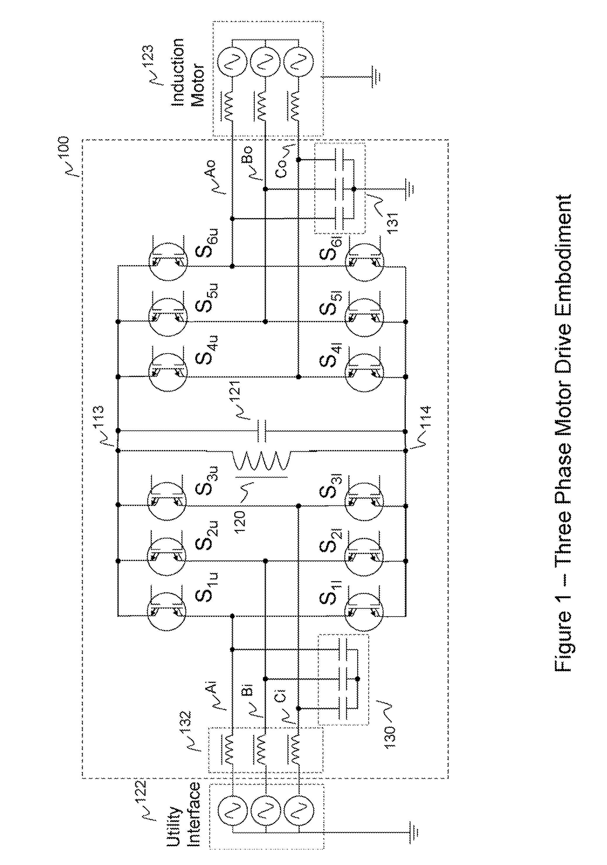
[0003] Numerous techniques have been proposed for electronic conversion of electric power from one form into another. A technique in common commercial usage for operating three phase induction motors at variable frequency and voltage off of fixed frequency and voltage utility power is the AC-DC-AC technique of the input diode bridge, DC-link capacitor, and the output active switch bridge, under PWM control, is shown in FIG. 3. This motor drive technique (“standard drive”) results in compact and low-cost motor drives, since no magnetic components are required and only six active switches are needed.
[0004] A number of difficulties exist with the standard drive, however. The input current, while nominally in phase with the input voltage, is typically drawn in pulses. These pulses cause increased electric losses in the entire electrical distribution system. The pulses also cause higher losses in the DC link capacitor. These losses reduce the efficiency of the drive, and also lessen the useful life of the DC link capacitor (commonly an Aluminum Electrolytic type), which has a limited life in any case. If the impedance of the source power is too low, the pulses may become so large as to be unmanageable, in which case it is necessary to add reactance in the input lines, which increases losses, size, cost, and weight of the drive. Also, the voltage available for the output section is reduced, which may lead to loss-producing harmonics or lower-than-design voltage on the output waveform when full power, full speed motor operation is called for.
[0005] Due to the fixed DC-link voltage, the output switches are typically operated with Pulse Width Modulation (PWM) to synthesize a quasi-sinusoidal current waveform into the motor, using the

Problems solved by technology

A number of difficulties exist with the standard drive, however.
These pulses cause increased electric losses in the entire electrical distribution system.
The pulses also cause higher losses in the DC link capacitor.
These losses reduce the efficiency of the drive, and also lessen the useful life of the DC link capacitor (commonly an Aluminum Electrolytic type), which has a limited life in any case.
If the impedance of the source power is too low, the pulses may become so large as to be unmanageable, in which case it is necessary to add reactance in the input lines, which increases losses, size, cost, and weight of the drive.
Also, the voltage available for the output section is reduced, which may lead to loss-producing harmonics or lower-than-design voltage on the output waveform when full power, full speed motor operation is called for.
While this does eliminate lower order harmonics, the resulting high frequency harmonics cause additional losses in the motor due to eddy current losses, additional IR (ohmic) heating, and dielectric losses.
These losses significantly increase the nominal losses of the motor, which reduces energy efficiency, resulting in higher motor temperatures, which reduces the useful life of the motor, and/or reduces the power available from the motor.
Additionally, due to transmission line effects, the motor may be subject to voltages double the nominal peak-to-peak line voltage, which reduces the life of the motor by degrading its insulation.
The applied motor voltages are also not balanced relative to ground, and may have sudden deviations from such balance, which can result in current flow through the motor bearings for grounded motor frames, causing bearing damage and reduced motor life.
The sudden voltage swings at the motor input also cause objectionable sound emissions from the motor.
This requirement leads to selection of switches with drastically reduced carrier lifetimes and limited internal gain.
This in turn decreases the conductance of each device, such that more silicon area is required for a given amount of current.
Additionally, the switches must be constructed to provide current limiting in the event of output line faults, which imposes additional design compromises on the switches which further increase their cost and losses.
Another problem with the stand

Method used


Image

  • Universal Power Converter
  • Universal Power Converter
  • Universal Power Converter

Examples


Embodiment Construction

[0067] The numerous innovative teachings of the present application will be described with particular reference to presently preferred embodiments (by way of example, and not of limitation).

Contrast with Other Approaches

[0068] DC-DC Buck-Boost converters employing resonant techniques to achieve soft switching are also shown in the patent literature (examples are U.S. Pat. No. 4,616,300, issued Oct. 7, 1986; U.S. Pat. No. 6,404,654, issued Jun. 11, 2002). These are not capable of DC-AC or AC-AC operation, and are also limited in their DC-DC range, in that the output DC voltage must be larger than some minimum in order to achieve zero voltage turn-on of the power switch. In contrast to this prior art, the inventions described below have no restrictions on the relative voltages between the input and output portals, and power transfer is bi-directional.

[0069] A “partial-resonant” 3 phase AC-AC Buck Boost converter is described in Kim et al., “New Bilateral Zero Voltage Switching AC / A...


PUM


Abstract

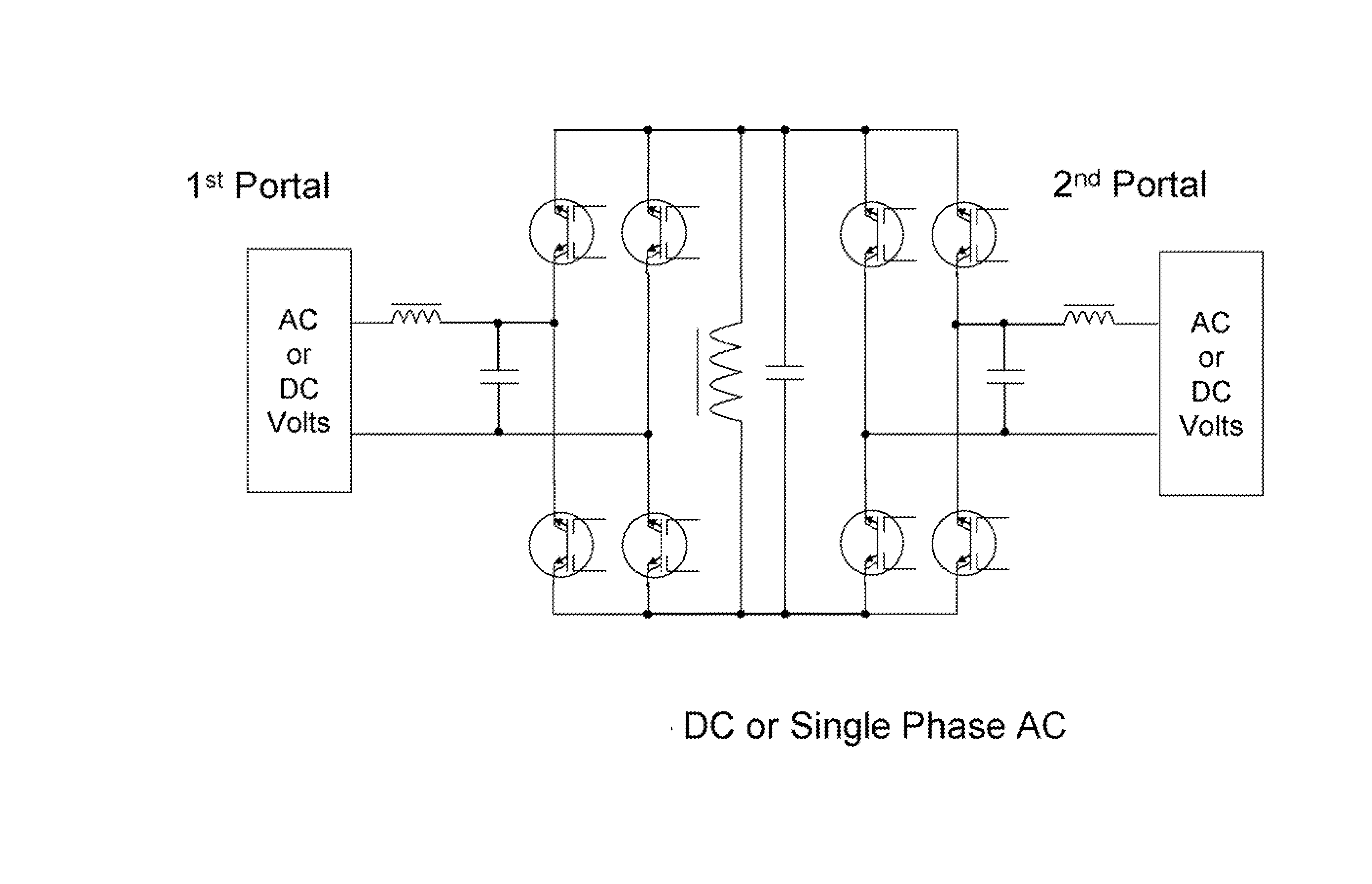
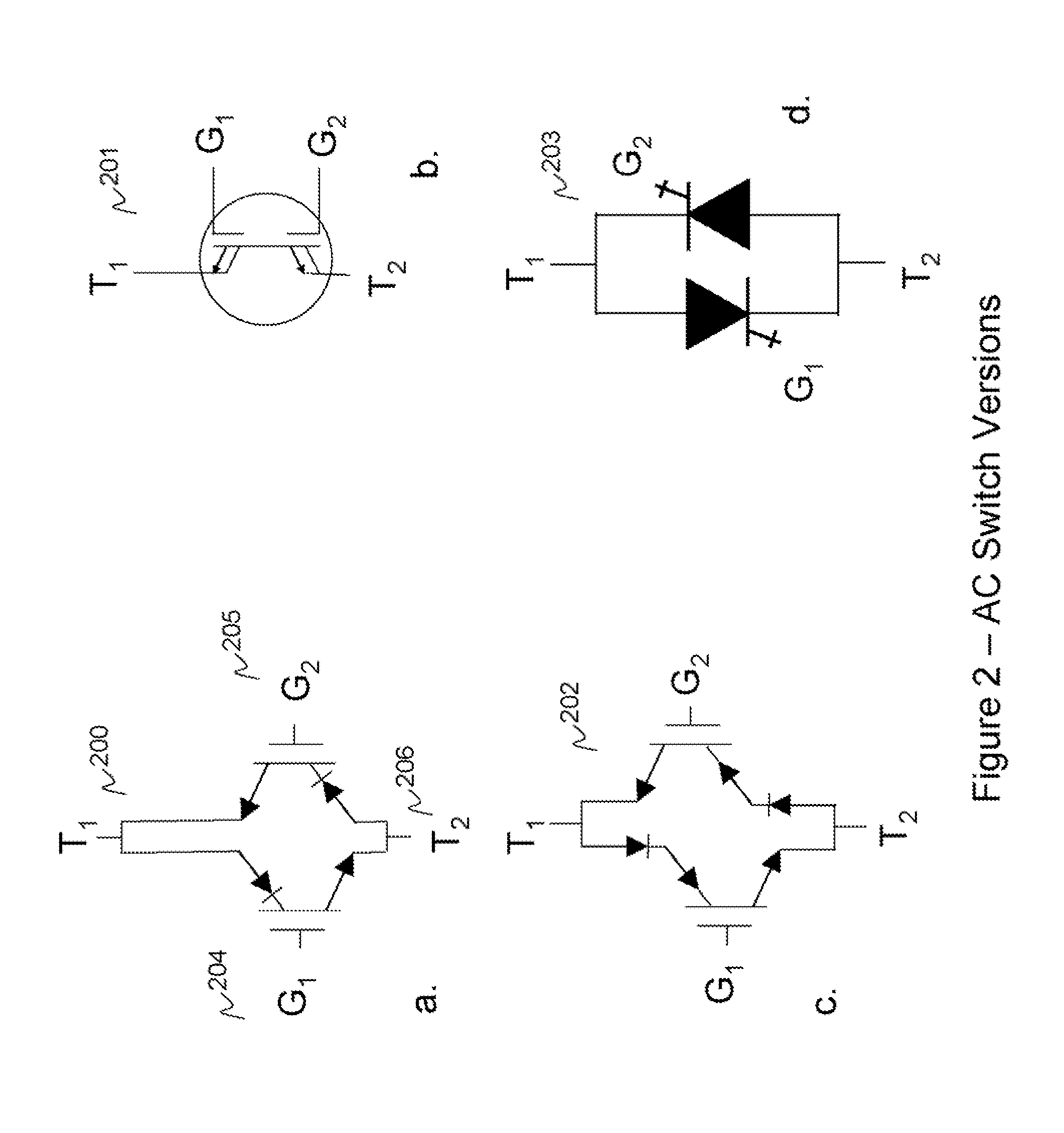
Methods and systems for transforming electric power between two or more portals. Any or all portals can be DC, single phase AC, or multi-phase AC. Conversion is accomplished by a plurality of bi-directional conducting and blocking semiconductor switches which alternately connect an inductor and parallel capacitor between said portals, such that energy is transferred into the inductor from one or more input portals and/or phases, then the energy is transferred out of the inductor to one or more output portals and/or phases, with said parallel capacitor facilitating “soft” turn-off, and with any excess inductor energy being returned back to the input. Soft turn-on and reverse recovery is also facilitated. Said bi-directional switches allow for two power transfers per inductor/capacitor cycle, thereby maximizing inductor/capacitor utilization as well as providing for optimum converter operation with high input/output voltage ratios. Control means coordinate the switches to accomplish the desired power transfers.

Description

CROSS-REFERENCE TO OTHER APPLICATION [0001] Priority is claimed from U.S. provisional application 60 / 811,191 filed Jun. 6, 2006, which is hereby incorporated by reference.BACKGROUND AND SUMMARY OF THE INVENTIONS [0002] The present application relates to electric power conversion, and more particularly to buck-boost converter circuits, methods and systems which can convert DC to DC, DC to AC, and AC-AC, and are suitable for applications including line power conditioners, battery chargers, hybrid vehicle power systems, solar power systems, motor drives, and utility power conversion. [0003] Numerous techniques have been proposed for electronic conversion of electric power from one form into another. A technique in common commercial usage for operating three phase induction motors at variable frequency and voltage off of fixed frequency and voltage utility power is the AC-DC-AC technique of the input diode bridge, DC-link capacitor, and the output active switch bridge, under PWM control...

Claims


Application Information

Patent Timeline
IPC IPC(8): H02M7/00
CPCH02M3/1582H02M3/33584H02M5/225H02M5/297H02M2007/4815Y02B70/1441H02M5/293H02M7/797H02M7/4815H02M7/4807Y02B70/10H02M5/10
Inventor ALEXANDER, WILLIAM
Owner CET GRP SA
Why Eureka
Try Eureka