
Methods and Devices for Improved Aeration From Vertically-Orientated Submerged Membranes

a vertical orientation, membrane technology, applied in the direction of membranes, filtration separation, separation processes, etc., can solve the problems of requiring substantial processing, aerating or facilitating processing of sewage, lack of water, etc., to improve shearing, improve shearing, and enhance aeration

Inactive Publication Date: 2008-01-24
VOST ENVIRONMENTAL TECH
View PDF12 Cites 53 Cited by
  • Summary
  • Abstract
  • Description
  • Claims
  • Application Information

AI Technical Summary

Benefits of technology

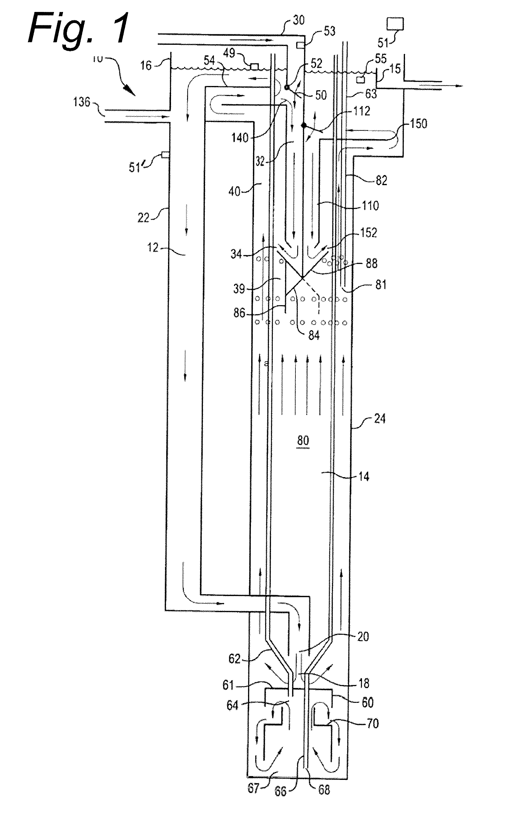
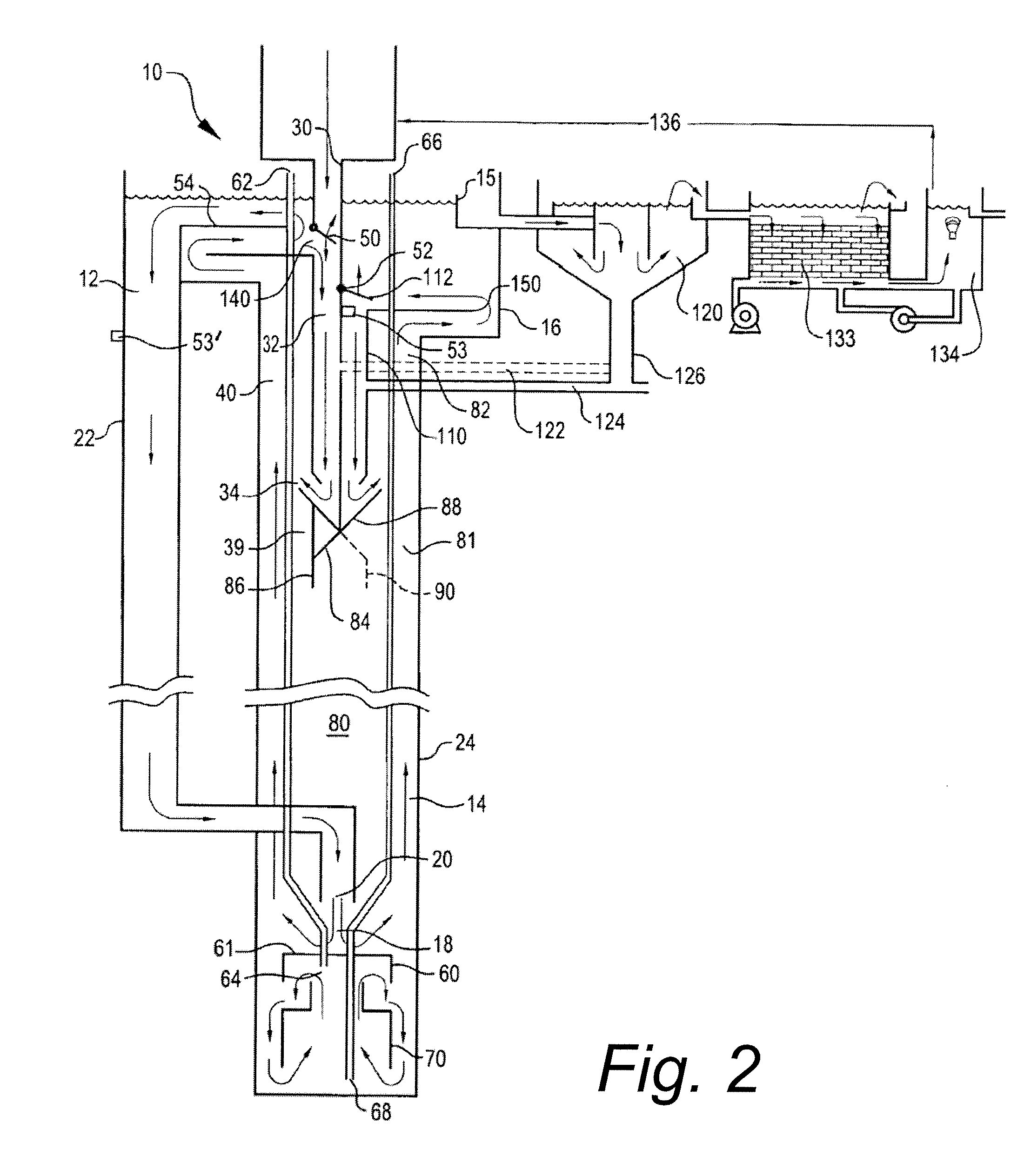
[0045] Submerged gas diffuser assemblies of the invention are configured to aerate liquids and liquid suspensions with substantially the same fine bubble aeration rate per unit area along the vertical height of the membrane. This substantially uniform fine bubble aeration rate enhances aeration by providing symmetric gas contact patterns from the vertically deployed gas permeable membranes into exposed liquids. Fine bubble streams are generated by an improved shearing effect of vertically flowing liquids across the vertically orientated membranes. The fine bubbles are smaller from the vertical membranes because the improved shearing from the vertically flowing fluids cleaves off smaller bubbles as they emerge from the membrane in contrast to the bubble nucleation or growth that occurs in horizontal membrane devices.
[0046] Adjusting the spatial configuration of gas permeable membranes varies aeration contact patterns and rates. Altering the liquid flow patterns around the vertically deployed membranes, and manipulating trans-membrane pressures across the membrane's vertical height, helps establish the formation of substantially uniform fine bubbles. Efficiency of gas exchange across membranes depends upon the liquid flow rates presented to the membrane assemblies, the contents within the liquids, the membrane surface area, and the rate of draining fluids from internal regions of the diffuser. Under some circumstances, the diffuser may under hydro-locking in which a selective occlusion of certain portions of membrane surface area generate gas impermeable regions. The membrane assemblies are designed to prevent, control, or mitigate membrane fouling and hydro lockup by effectively draining fluids from internal regions of the diffuser to mitigate hydro-locking that might develop.
[0048] The gas is delivered to internal regions of the membrane resulting in the distribution of fine gas bubbles substantially evenly throughout the membrane's vertically orientated surface. Depending on membrane design, the gas bubbles are distributed evenly by the membrane without a “wetting out” or hydro blocking effect, and in other cases when wetting out occurs, the diffuser designs advantageously allows the countering of wetting out events. That is, when hydro blocking or locking occurs, diffuser designs provide for the mitigation, reduction, and elimination of wetting out events.
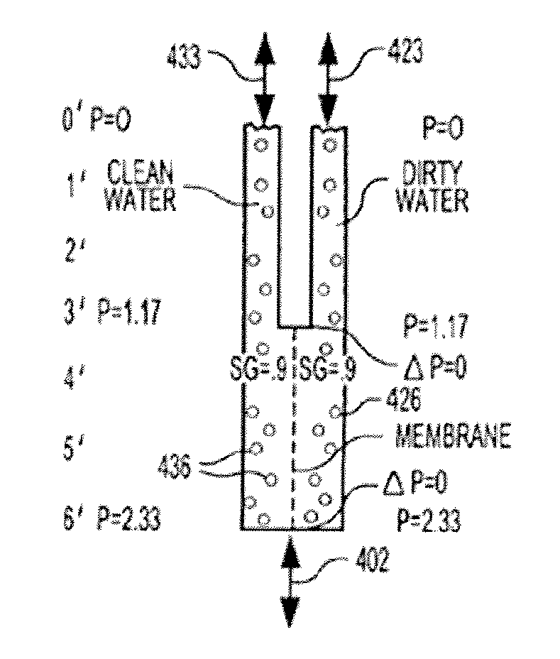
[0051] Yet other embodiments of the invention also provides methods and devices having improved through-put and operating life of submerged membranes used in biological treatment of waste waters, and increased time between cleaning and maintenance of the membranes. More specifically, the invention relates to membrane separation methods and devices employing a selective, semi-permeable, microporous, or other partitioning membrane for processing, refining, and / or treating liquid compositions, for example membrane waste-water purification processes and apparatus. Other aspects of the invention improve diffusion of a gas in a liquid by creating a substantially uniform pressure differential between opposite sides of a membrane.
[0061] The methods and devices of the invention are broadly applicable within fluid treatment methods and devices. In various treatment processes and devices where membranes are employed, where fluids containing solids tend to foul the membranes or where clean fluids have a slow permeate rate, the invention provides substantial advantages. In the case of drinking water, membrane run time can be extended by adding CO2 to the first and / or second fluids, which is also desirable for pH adjustment of the water. Industrial filters, for example filters to remove sediment and precipitated protein from chilled beer, this will also be advantageous for recarbonation prior to bottling. Inert gas filtration, such as gasoline purification using nitrogen gas, is also amenable to optimization using the methods and devices of the invention. In this case, a gas recovery system is provided downstream of the membrane, and a repressurization system may also be employed. Nitrous oxide may also be employed as an added gas (e.g., as a gas introduced into the second fluid) to yield desired fuels / additives.

Problems solved by technology

Many of these undeveloped areas lack sufficient water for consumption, irrigation and similar purposes, necessitating reclamation and reuse of available water resources.
Residential wastewater has a high water content, but requires substantial processing before it can be reused because of the human waste and other contaminants mixed with it.
Unfortunately, this system suffers from a number of shortcomings that make it inefficient.
In particular, the system incorporates a relatively crude sedimentation system that merely allows the influent sewage to separate and does not aerate or facilitate processing of the sewage in any other way.
The injected oxygen-containing gas dissolves readily under pressure in the liquor in the plug flow zone where there is localized back mixing resulting in a slow net downward movement of liquor.
The old Secondary Biological treatment standard of 30 mg / L BOD and 30 mg / L TSS is no longer adequate in many jurisdictions and limits are now often placed on nitrogen and phosphorus as well.
Incorporation of an anaerobic processing step for phosphate removal is typically done in a separate reactor—due to the long fermentation time required for volatile fatty acid production.
Furthermore, phosphorus removal in single mixed liquor systems is difficult to implement because the phosphate rich biomass produced in the aerobic portion of the process should not contact the anaerobic fermentation reactor product due to the risk of re-solubilizing the entrapped phosphate.
Due to the slow overall rate of treatment, these single mixed liquor systems are called extended aeration systems and are quite energy intensive.
In addition, there remains an unfulfilled need for wastewater treatment systems and methods that satisfy these expanded functions while minimizing the costs and environmental impacts that attend conventional wastewater treatment plant installation and operation.
Historically, membrane separation processes or systems have not been considered cost effective for water treatment due to the adverse impacts that membrane scaling, membrane fouling, membrane degradation and the like impose on the efficiency of removing solutes from aqueous water streams.
The moisture content in the soil in some areas is already less than in the “dirty thirties.” The primary factor in progressive water rationing restrictions has been attributed to the inability of existing potable water treatment plants to produce enough potable water to satisfy increasing domestic and commercial demands.
In addition, membrane prices used in modern treatment and processing plants have been decreasing, and will decrease even more significantly over the next decade.
This cost includes amortization of capital, operating and maintenance costs based on year-round operations.
Existing reactors typically are not operational during membrane cleaning, causing a temporary and reoccurring loss of wastewater treatment capacity.
Further, cleaning often involves use of expensive, specialized chemicals requiring compliance with environmental regulations in use and disposal.

Method used


Image

  • Methods and Devices for Improved Aeration From Vertically-Orientated Submerged Membranes
  • Methods and Devices for Improved Aeration From Vertically-Orientated Submerged Membranes
  • Methods and Devices for Improved Aeration From Vertically-Orientated Submerged Membranes

Examples


embodiment 880

[0385]FIG. 27A illustrates a gas ribbed diffuser embodiment 880 having a flexible diaphragm 921, air ports 924 equipped with a panel of manometers lines 928 to obtain pressure measurements of a spiral pattern of tapped holes 936 and to permit the observation of emerging bubbles within observation lanes 932 mounted on the outside of the diffuser 880. The holes 936 are space in 5-hole increments per observation lane 932 in the spiral pattern, are approximately 0.030 inches in diameter, and spaced approximately 0.3 inches apart. The ribbed diffuser is tapped for manometer pressure measurements circumferentially for a plurality of 0.030″ diameter holes tapped at different elevations. The spiral pattern allows for direct observation of air-bubble streams at different elevations due to the lateral displacement along the spiral pathway. Otherwise, had the holes been place more or less in horizontal ascending rows, the simultaneous emerging of multiple bubble streams would have obscured or ...

embodiment 1300

[0428] The alternate diffuser embodiment 1300 combines the cone-shaped diffuser 760 of FIG. 23A with a porous gas diffuser cylinder membrane 1330 that extends from the conically shaped diffuser membrane 720. The cone-shape diffuser includes the conical support element 764 substantially similar to that illustrated in FIG. 23A that also includes a cylindrical support extension 764A that is continuous with the conical support element 764. Porous surface 720 extends from the conical region onto the cylinder. Located in-between the cylinder 720 porous region and the cylinder support extension 764A is a longer version of the gas impermeable flexible diaphragm 772 that extends over the conical support 764 onto the cylindrical extension support 764A. 1330. The cylinder extension 1330 is capped with the bubble barrier 1340. Particular embodiments of the bubble barrier 1340 includes an inverted cone shape and may be made of metal materials to thwart gas accumulation underneath the cylinder ex...


PUM

PropertyMeasurementUnit
pore sizeaaaaaaaaaa
pore sizeaaaaaaaaaa
diameter×10aaaaaaaaaa

Abstract

Submerged gas diffuser assemblies configured to aerate liquid suspensions in reservoirs or deep shafts with enhanced aeration contact patterns and adjustable aeration rates. Aeration contact patterns and rates are varied by the adjusting the spatial configuration of gas permeable membranes, altering the fluid flow patterns around the membranes, manipulating trans-membrane pressures across membranes, varying the sequence of aeration of liquid within the fluid flow patterns, expanding the membrane surface area, and / or by selectively occluding certain portions of membrane surface area of the membrane assemblies. The membrane assemblies are designed to prevent, control, or mitigate membrane fouling and hydro lockup.

Description

RELATED APPLICATIONS [0001] This application claims priority to U.S. Provisional Patent Application No. 60 / 778,164 filed Mar. 1, 2006. This application also claims priority as a continuation in part of International application No. PCT / US2005 / 010976 filed Mar. 31, 2005 (corresponding to WIPO publication No. WO / 2005 / 100264, published Oct. 27, 2005), which in turn relates priority of this application back to, and is a continuation in part of, U.S. patent application Ser. No. 10 / 895,432 filed Apr. 6, 2004 (corresponding to U.S. Publication No. 2005 / 0218074 A1, published Oct. 6, 2005), and also claims priority from U.S. Provisional Patent Application No. 60 / 572,387, filed May 18, 2004. The complete priority lineage set forth above is claimed in this application, and each of the foregoing priority applications and corresponding publications are incorporated herein by reference in its entirety for all purposes. FIELD OF THE INVENTION [0002] The present invention relates to methods and dev...

Claims


Application Information

Patent Timeline
Patent Type & Authority Applications(United States)
IPC IPC(8): B03D1/14B01D21/30C02F3/12B01D35/00
CPCB01D61/18B01D2313/26B01D2315/06C02F1/20C02F1/24C02F11/121C02F1/5236C02F1/56C02F1/76C02F3/1273C02F3/208C02F1/32Y02W10/10
Inventor POLLOCK, DAVID C.BRODD, GREGORY B.
Owner VOST ENVIRONMENTAL TECH
Learn More