
An Apparatus for Producing a Single Crystal

Inactive Publication Date: 2008-02-14
SHIN-ETSU HANDOTAI CO LTD
View PDF2 Cites 10 Cited by
  • Summary
  • Abstract
  • Description
  • Claims
  • Application Information

AI Technical Summary

Benefits of technology

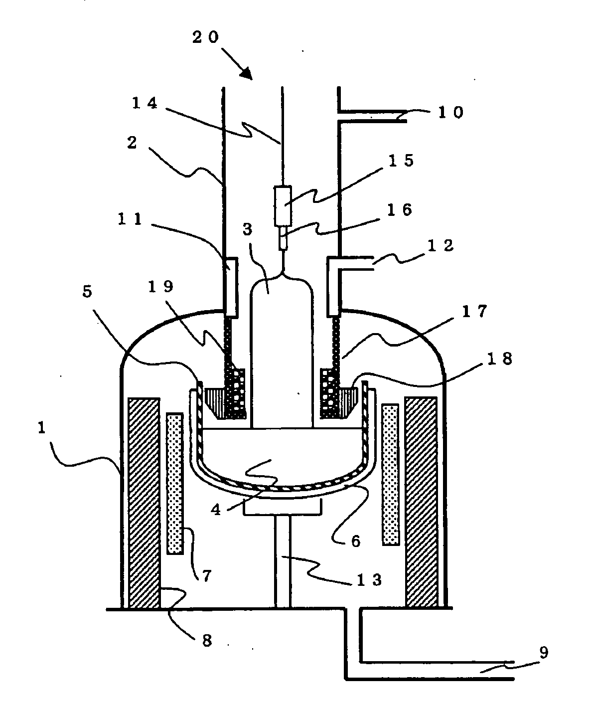
[0021] The present invention has been made to solve the above problems. A main object of the present invention is to provide a single crystal-producing apparatus by which when a CZ silicon single crystal is grown, a silicon single crystal having a desired defect region being uniform in a plane can be effectively produced by controlling F / G along the radial direction in the single crystal plane constantly to be a predetermined value, and further contamination with impurities of Fe and Cu is prevented, and thereby a silicon single crystal of high quality can be produced.

Problems solved by technology

Furthermore, it has been found that a region in which defects detected by Cu deposition treatment exist in some part of Nv region generating easily oxygen precipitation after a thermal oxidation treatment exist.
If V region, OSF region, or I region exists in the wafer plane as well as N region, there is a danger of triggering significant degradation of electric characteristics.
Therefore, improvement of uniformity of defect quality in the wafer plane has been a problem.
However, if the distance from the melt surface to the lower end of the gas flow-guide cylinder is excessively enlarged, the effects by straightening flow of the inert gas, such as lowering of, the control of the oxygen concentration in the crystal and the pulling rate for a N region crystal, are caused.
On the other hand, as an important factor for improving yield in the device production in recent years, yield improvement of the devices in the peripheral portion of the wafer has become a problem.
However, recently, it has been revealed that Fe, Cu, or the like, for example, released from the gas flow-guide cylinder attaches to the single crystal in the growth, and diffuses inside, and thereby contamination with impurities of heavy metals and so forth is caused in the crystal peripheral portion.
However, if heavy metal components such as Fe and Cu are released from the gas flow-guide cylinder when a silicon single crystal is grown, these heavy metal components attach to the single crystal surface in the growth, and diffusion of Fe and Cu is caused from the crystal periphery in the subsequent process of being cooled down from a high temperature to a room temperature, and metal contamination becomes caused in the peripheral portion of the single crystal, particularly, in the peripheral portion within 10% of the diameter from the periphery of the single crystal.
Among them, there is a problem that a heat insulating material made of carbon felt has lower purity than that of a graphite member or the like, and additionally, fibers are easily scattered in the growth of the silicon single crystal, and thereby contamination due to Fe, Cu, or the like, is easily caused.

Method used


Image

  • An Apparatus for Producing a Single Crystal
  • An Apparatus for Producing a Single Crystal
  • An Apparatus for Producing a Single Crystal

Examples


example 1

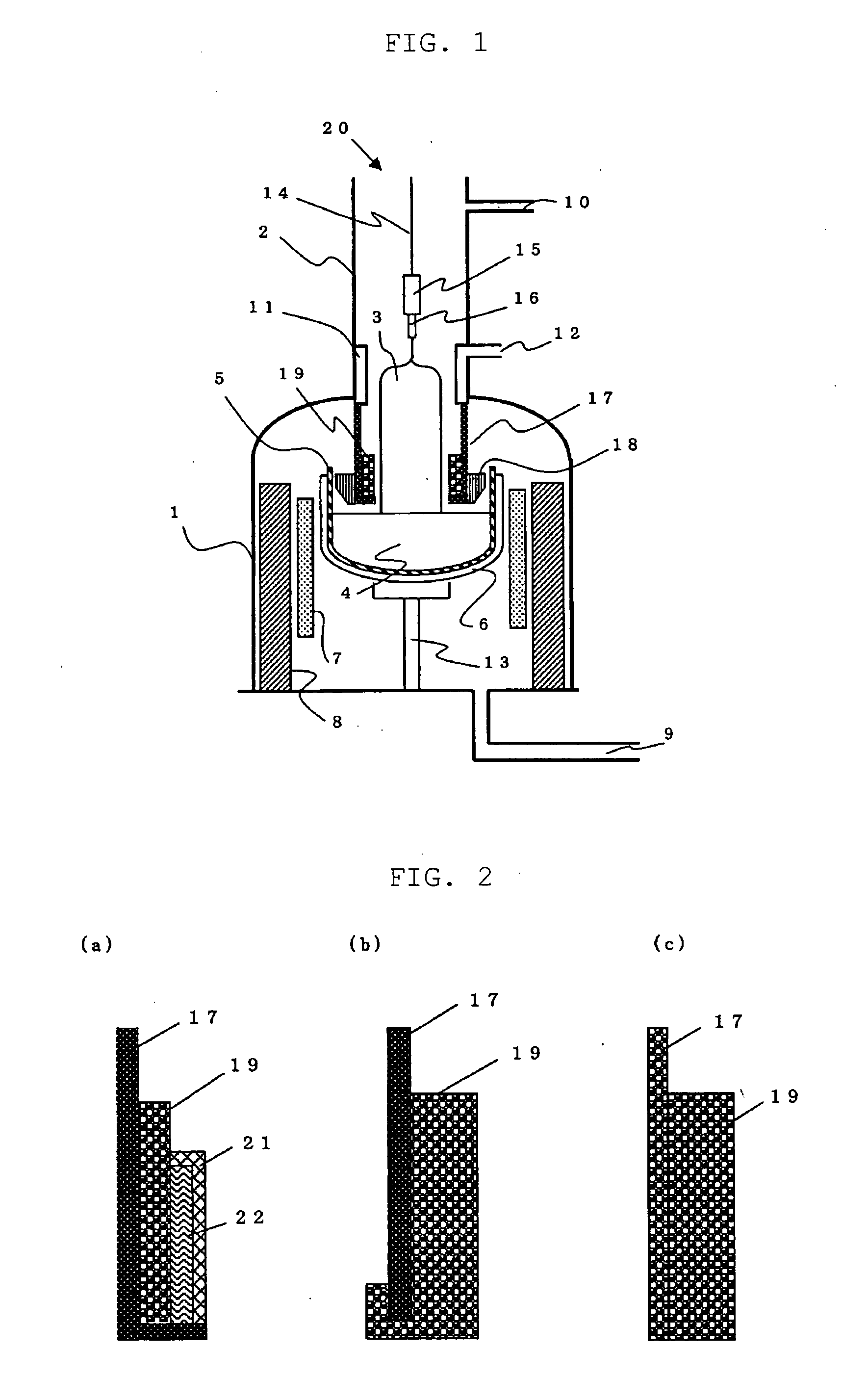
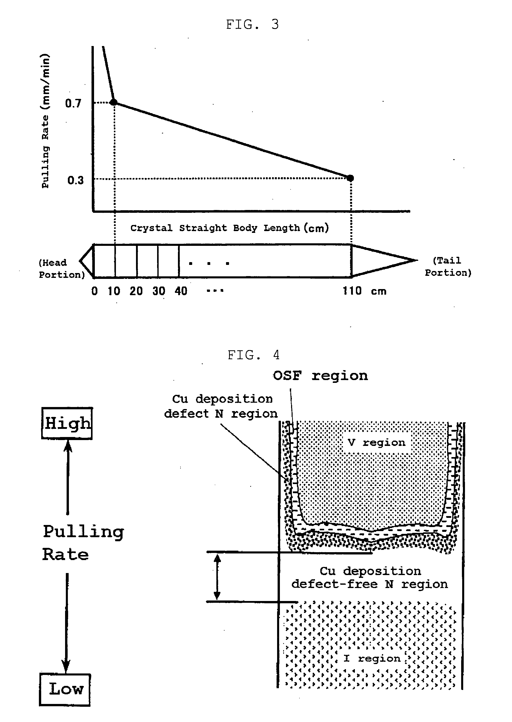
[0062] By using the apparatus 20 for pulling a single crystal as shown in FIG. 1, 150 kg of raw material polycrystalline silicon was charged in the quartz crucible 5 with a diameter of 24 inch (600 mm), and a silicon single crystal with a diameter of 8 inch (200 mm), an orientation of , and an oxygen concentration of 22 to 23 ppma (ASTM'79), was pulled by CZ method. Inside the lower end of the gas flow-guide cylinder 17 made of isotropic graphite that was suspended from the ceiling of the pulling chamber 2 so as to surround the pulled single crystal along the single crystal growth direction, there was provided the bubble-containing quartz member 19 having bubbles of diameters of 30 to 120 μm, the bubble density of 2×10⁵ number / cm3 to 3×10⁵ number / cm3, the logarithmic viscosity of 12 poise in 1250° C., the occupied rate of 90% with respect to the inside surface area, the wall thickness of 10 mm, and a height of 150 mm. In addition, the density of the bubbles contained in the quartz m...

example 2

[0078] The same apparatus for pulling a single crystal as Example 1 was used except using the gas flow-guide cylinder provided with the bubble-containing quartz member 19 having bubbles of diameters of 30 to 120 μm, the bubble density of 5×10⁴ number / cm3, the logarithmic viscosity of 10 poise in 1250° C., the occupied rate of 90% with respect to the inside surface area, the wall thickness of 10 mm, and a height of 150 mm, inside the lower end of the gas flow-guide cylinder 17 placed in the apparatus 20 for pulling a single crystal. And, a silicon single crystal with a diameter of 8 inch (200 mm), an orientation of , and an oxygen concentration of 22 to 23 ppma (ASTM'79), was pulled by CZ method. In addition, as the condition of the pulling rate when the single crystal was pulled, in the same manner as Example 1, the pulling rate from 10 cm of the straight body of the single crystal to 110 cm thereof was controlled to be reduced gradually from the crystal head portion to the tail por...


PUM


Abstract

The present invention is an apparatus for producing a single crystal by which a silicon single crystal is grown by Czochralski method, comprising, at least, a gas flow-guide cylinder which is disposed so as to surround the silicon single crystal in a chamber for growing the single crystal in order to straighten flow of a gas introduced into the chamber, and a quartz member containing bubbles that is provided inside the gas flow-guide cylinder. Thereby, there can be provided a single crystal-producing apparatus by which when a CZ silicon single crystal is grown, a silicon single crystal having a desired defect region being uniform in a plane can be effectively produced by controlling F / G along the radial direction in the single crystal plane constantly to be a predetermined value, and further contamination with impurities of Fe and Cu is prevented, and thereby a silicon single crystal of high quality can be produced.

Description

TECHNICAL FIELD [0001] The present invention relates to an apparatus for producing a single crystal by which a silicon single crystal is grown by Czochralski method (hereinafter, called as CZ method), more specifically to an apparatus for producing a single crystal by which when a single crystal is pulled, the temperature gradient in the vicinity of the solid-liquid interface along the direction of the crystal growth axis can be controlled to be uniform in the radial direction of the silicon single crystal, and thereby a silicon single crystal having a desired defect region being distributed uniformly in a plane can be effectively produced, and a silicon single crystal of high quality can be produced so that contamination due to impurity metal elements is small. BACKGROUND ART [0002] As a single crystal used as a substrate of a semiconductor device, for example, there is a silicon single crystal, and it is mainly produced by CZ method. In recent years, semiconductors have become hig...

Claims


Application Information

Patent Timeline
IPC IPC(8): C30B15/00
CPCC30B15/14Y10T117/1032C30B29/06C30B15/20C30B15/00
Inventor SAKURADA, MASAHIRO
Owner SHIN-ETSU HANDOTAI CO LTD
Learn More