Highly Durable Electrode Catalyst Layer

Active Publication Date: 2008-04-24
ASAHI KASEI KK
View PDF7 Cites 17 Cited by
  • Summary
  • Abstract
  • Description
  • Claims
  • Application Information

AI Technical Summary

Benefits of technology

[0039] The highly durable electrode catalyst layer and highly durable membrane electrode assembly according to the present invention can provide a highly durable fuel cell which has excellent chemical stability, and which has low discha

Problems solved by technology

However, when a fuel cell employing a conventional perfluorocarbon sulfonic acid resin membrane as the polymer electrolyte membrane and a membrane electrode assembly consisting of a conventional electrode catalyst layer is operated for a long time under high temperature and low humidity conditions, the problems arise that cross leakage occurs as a result of the formation of pinholes in the polymer electrolyte membrane, and fluorine ions elute out.
Consequently, sufficient durability cannot be achieved.
However, even with these methods it has not been possible to suppress the elution of fluorine ions

Method used


Image

  • Highly Durable Electrode Catalyst Layer
  • Highly Durable Electrode Catalyst Layer
  • Highly Durable Electrode Catalyst Layer

Examples


example 1

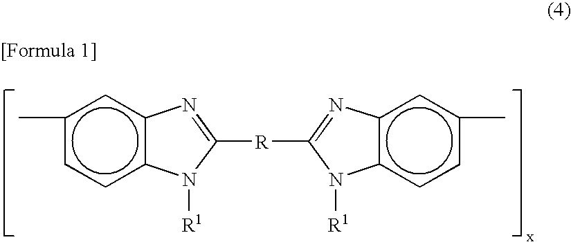
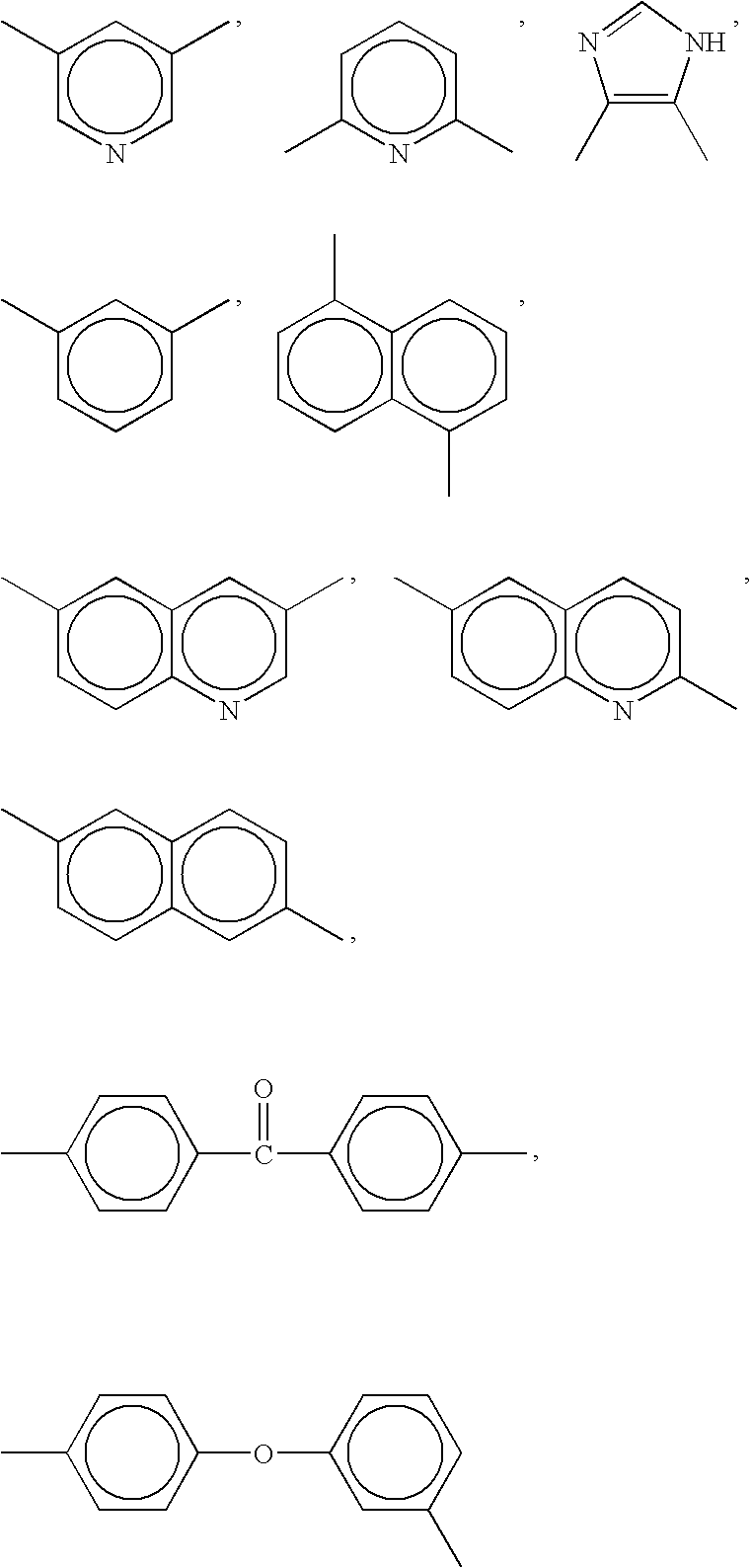
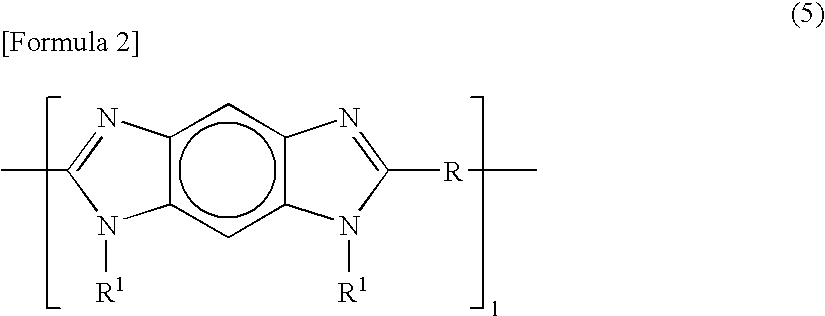
[0167] The example will be illustrated below. In this case, a highly durable electrode catalyst layer was used which was composed of perfluorocarbon sulfonic acid resin (hereinafter, “PFSA”) represented by [CF2CF2]0.812—[CF2—CF(—O—(CF2)2—SO3H)]0.188, poly[2,2′-(m-phenylene)-5,5′-bibenzimidazole] (hereinafter, “PBI”) sodium salt (hereinafter, “PBI-Na”) as a polyazole-based compound, and a platinum catalyst-loaded carbon as a composite particle, wherein the composite particle / PFSA / PBI-Na weight ratio was 70.2 / 29.5 / 0.3.

[0168] First, the methods for producing the PFSA and dissolving the PFSA in a protic solvent will be described.

[0169] A perfluorocarbon polymer (MI: 3.0) consisting of tetrafluoroethylene and CF2═CFO(CF2)2—SO2F was synthesized as a precursor polymer for the PFSA. Then, using an extruder, the synthesized polymer was extruded from a round mouthpiece at 270° C., and cooled with room temperature water. The polymer was then cut into cylindrical pellets of 2 to 3 mm in diame...

example 2

[0181] A membrane electrode assembly will be described below, which was fabricated using the same anode catalyst layer and cathode catalyst layer as produced in Example 1, and the following polymer electrolyte membrane.

[0182] 37.3 g of the above-described perfluorocarbon sulfonic acid resin solution (AS1) was evenly spread over a 20 cm wide and 20 cm long petri dish made from SUS 316, and then dried over a hotplate for 2 hours at 80° C. The resultant membrane was then further heat treated for 1 hour at 180° C. in a hot-air oven. After cooling, the membrane was peeled off from the dish, and then dipped for 8 hours in an aqueous 2N hydrochloric acid solution (manufactured by Wako Pure Chemical Industries, Ltd.) having a temperature of 25° C. The membrane was washed with acid, and then thoroughly washed with ion exchanged water. The membrane was subsequently dried under a 25° C., 35% RH environment, to thereby obtain a transparent, 50 μm thick polymer electrolyte membrane.

[0183] Usin...

example 3

[0185] An example will be described below. In this case, a highly durable electrode catalyst layer was used which was composed of the same PFSA, PBI-Na, and a composite particles as in Example 1, wherein the composite particle / PFSA / PBI-Na weight ratio was 68.2 / 29.2 / 2.6. This highly durable electrode catalyst layer was produced using the following electrolytic polymer solution B.

[0186] First, an alkali metal hydroxide and PBI were dissolved in the following manner in a protic solvent. Specifically, 0.0324 g of PBI (manufactured by Sigma-Aldrich Japan K.K., having a weight average molecular weight of 27,000) was dipped into a mixed solution consisting of 0.1394 g of aqueous NaOH of 16% by weight and 10 g of ethanol, and the resultant solution was stirred for 1 hour while heating at 80° C. Once the PBI had dissolved in the solvent, 5.3487 g of ethanol was added, to thereby obtain a red-brown polybenzimidazole solution. This solution is referred to as polyazole resin solution (BS2).

[0...


PUM

PropertyMeasurementUnit
Fractionaaaaaaaaaa
Percent by massaaaaaaaaaa

Abstract

An electrode catalyst layer characterized by comprising composite particles comprising electrode catalyst particles supported on electrically conductive particles, a perfluorocarbonsulfonic acid resin (component A) and a polyazole compound (component B), the content of the composite particles being 20 to 95% by weight, the total weight of component A and component B being 5 to 80% by weight, the weight ratio between component A and component B (A/B) being 1 to 999.

Description

TECHNICAL FIELD [0001] The present invention relates to an electrode catalyst layer for a solid polymer fuel cell. BACKGROUND ART [0002] Fuel cells generate electric energy by an electrochemical within the cell reaction between a fuel (hydrogen source) and an oxidant (oxygen). Specifically, the chemical energy of the fuel is directly converted into electric energy. Examples of fuel sources which can be used include pure hydrogen and compounds containing hydrogen element, such as petroleum, natural gases (such as methane) and methanol. [0003] Fuel cells have the following advantageous characteristics. A fuel cell itself employs no mechanical parts and, therefore, it generates little noise. Further, in principle, a fuel cell can semipermanently continue to generate electricity if fuel and oxidant are continuously supplied from outside of the cell. [0004] Electrolytes can be classified into liquid electrolytes and solid electrolytes. A fuel cell which employs a polymer electrolyte memb...

Claims


Application Information

Patent Timeline
IPC IPC(8): H01M8/10B01J31/10H01M4/88
CPCH01M4/9075H01M8/1004H01M8/1023H01M8/103H01M4/9016H01M8/1044Y02E60/521H01M4/8605H01M8/1039Y02E60/50H01M4/86H01M8/02H01M8/10
Inventor MIYAKE, NAOTO
Owner ASAHI KASEI KK
Why Eureka
Try Eureka