Member for Semiconductor Device and Production Method Thereof

Inactive Publication Date: 2008-05-29
ALLIED MATERIAL
View PDF6 Cites 25 Cited by
  • Summary
  • Abstract
  • Description
  • Claims
  • Application Information

AI Technical Summary

Benefits of technology

[0066]As described above, in accordance with the present invention, since it is possible to bond a superficial layer containing aluminum or aluminum alloy and having excellent toughness on the first surface and second surface which are outer faces of the base material formed of an aluminum-silicon carbide composite material in a thick manner without occurrence of defects, it is possible to form a plating layer of hig

Problems solved by technology

However, Mo has problems of high costs and a high specific gravity.
However, there still remain several problems in using an Al—SiC composite material as a member for a power device, and an Al—SiC composite material is not regularly adopted except for in certain devices.
For example, when an Al—SiC composite material is used as a member for a power device which is one exemplary application of a member for a semiconductor device, the following problems arise.
For example, when the resultant plating has a defect, a void occurs in solder, which may deteriorate performance and shorten the lifetime of the semiconductor device.
Plating on the surface of the Al—SiC composite material faces the problem that porous defects occur in the case of an Al—SiC composite material produced by sintering or self-infiltration, and cracking occurs in SiC in the case of an Al—SiC composite material produced by sintering plus forging, and shedding of SiC particles occurs due to grinding which is a pre treatment in any of these production methods.
Therefore, there is a problem that it is impossible to form a plated layer with high quality on the surface of the member for a semiconductor device.
(2) With increased performance and decreased size of power device, it becomes more apparent that low heat conductivity at a high temperature of the member for a semiconductor device decreases the performance of the device, and shortens lifetime.
A member for a semiconductor device is fixed to a radiator of Al alloy with screw, however, since the Al—SiC composite material is fragile, it may break, and breaking occur particularly at the site of screwing, leading device failure.
When a solder material having less ductility is bonded with a material having high Young's module, heat stress concentrates the solder part, and breaking may occur, leading the problem of shortening device lifetime.
In particular, since a Pb-free solder material is inferior in ductility to the Pb-containing solder material, this problem tends to be further closed up.
In such a member for a semiconductor device, when plating is conducted on the surface, it is impossible to prevent plating defects caused by shedding of SiC, porous defects, cracking of SiC and the like, so that voids occur in solder, and the performance of semiconductor device may decrease and lifetime may be shortened.
Further, such a measure is insufficient for solving the problems of breaking at the site of screwing and of breaking of solder due to concentration of heat stress.
When such a material is used for a member for a semiconductor device, voids will occur in solder due to high porosity and plating defects, which may deteriorate the performance of semiconductor device and shorten the lifetime.
Further, such a measure is insufficient for solving the problems of breaking at the site of screwing and of breaking of solder due to concentration of hea

Method used


Image

  • Member for Semiconductor Device and Production Method Thereof
  • Member for Semiconductor Device and Production Method Thereof
  • Member for Semiconductor Device and Production Method Thereof

Examples


example 1

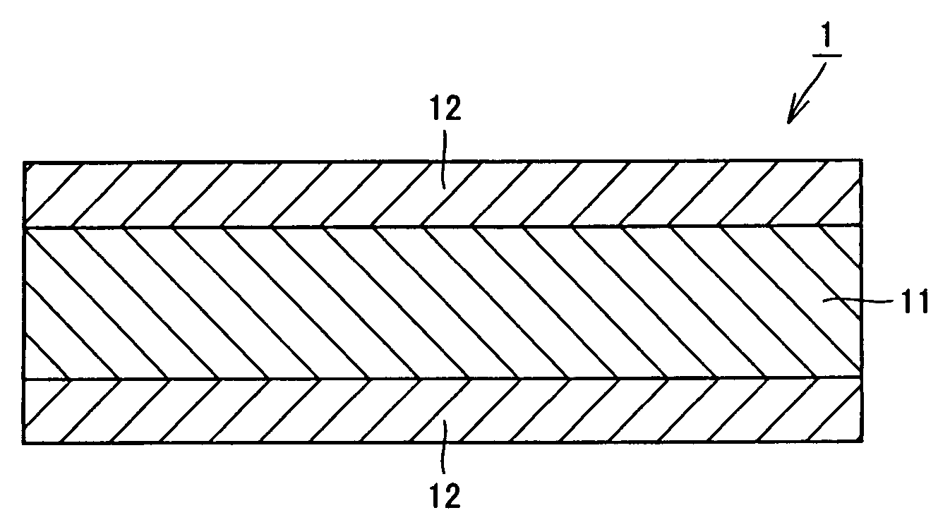
[0114]Aluminum (Al) powder having an average particle diameter of 10 μm and silicon carbide (SiC) powder having an average particle diameter of 15 μm were mixed so that the content of SiC was as shown in Table 1 while the mixing ratio was varied, and molding was carried out while the resultant mixed powder was placed on the top and bottom faces of an aluminum plate of JIS (Japanese Industrial Standards) 1050, or in other words, in the condition that the mixed powder was sandwiched by an aluminum plate having a thickness shown in Table 1, to prepare a molded body (molding step). Molding of mixed powder was carried out so that the molding pressure was 2 ton / cm2 (2×98 MPa) by applying a load of 72 tons on the powder using 100-ton pressing machine. The molded body obtained in this manner was heated and compressed while it was heated to a temperature of 600° C. so that compression pressure was 2 ton / cm2 (2×98 MPa) by application of a load of 72 tons on the molded body with the use of the...

example 2

[0137]Each sample in Example 1 was drilled while lubricant oil was applied to form a hole of 10.5 mm in diameter by means of a drill, and a bolt of M10 was inserted, and a nut was fastened at a torque of 10 kgf in (98 N·m). Breaking occurred in comparative examples 5 to 7, while breaking was not observed in inventive examples 5 to 7 even torque was elevated to 15 kgf·μm (15×9.8 N·m). The crystal structure of an aluminum layer serving as a superficial layer in inventive examples 5 to 7 was observed, and the average crystal particle diameter was 84 μm, 158 μm, and 34 μm, respectively.

example 3

[0138]Samples was prepared in a similar manner as in Example 1 at an SiC content of 60% by mass, with variable the average particle diameter of SiC powder of 5 μm, 10 μm, 80 μm, 150 μm and 200 μm, and a variable thickness of an aluminum layer of 0.050 mm, 0.100 mm, 0.500 mm, 1.000 mm, 2.000 mm, and 2.500 mm. Each sample was evaluated for heat conductivity at a temperature of 100° C., variation in a thickness of an Al layer, and ratio of warp in the same manner as described in Example 1. The results are shown in Table 2, Table 3 and Table 4.

TABLE 2Heat conductivity [W / m · K]SiCaverageparticlediameterThickness of Al layer [mm][μm]0.0500.1000.5001.0002.0002.50051811821801821831871018720620020320120080186198183185198201150185200200205198210200190190190198197205

TABLE 3Variation in thickness of Al layer [%]SiCaverage particleThickness of Al layer [mm]diameter [μm]0.0500.1000.5001.0002.0002.50051098543103015121063804020151273150552518148420080362520146

TABLE 4Ratio of warp (Y / X) [%]SiCavera...


PUM

PropertyMeasurementUnit
Temperatureaaaaaaaaaa
Fractionaaaaaaaaaa
Fractionaaaaaaaaaa

Abstract

A member for a semiconductor device of low price, capable of forming a high quality plating layer on a surface, having heat conductivity at high temperature (100° C.) of more than or equal to 180 W/m·K and toughness that will not cause breaking due to screwing, and will not cause solder breaking due to heat stress when it is bonded to other member with solder, and a production method thereof are provided. A member for a semiconductor device (1) having a coefficient of thermal expansion ranging from 6.5×10⁻⁶/K to 15×10−6/K inclusive, and heat conductivity at 100° C. of more than or equal to 180 W/m·K, has: a base material (11) formed of an aluminum-silicon carbide composite material starting from powder material in which particulate silicon carbide is dispersed in aluminum or aluminum alloy, and the content of the silicon carbide is from 30% by mass to 85% by mass inclusive; and a superficial layer (12) containing aluminum or aluminum alloy starting from a melt material bonded on top and bottom faces of the base material (11).

Description

TECHNICAL FIELD[0001]The present invention generally relates to a member for a semiconductor device and a production method thereof, and more specifically to a member for a semiconductor device serving as a heat radiator member such as a heat spreader or lid member constituting a semiconductor device, and a production method thereof.BACKGROUND ART[0002]For example, in a power device which is a semiconductor device of high performance, for insulation of a silicon (Si) chip serving as a semiconductor integrated circuit device (IC), such a structure is employed that an Si chip is soldered on aluminum nitride (AlN) sintered substrate having copper (Cu) or aluminum (Al) on its surface, and under the AlN sintered substrate; a member for a semiconductor device which is an object of the present invention is soldered; and the member for a semiconductor device is fixed with screw to a radiator formed of aluminum alloy in order to cool the member for a semiconductor device with water.[0003]At ...

Claims


Application Information

Patent Timeline
IPC IPC(8): H01L23/14C22C1/05B22F3/14B22F7/04
CPCB22F7/04H01L2924/01019B22F2999/00C22C1/1084C22C29/065C22C32/0063H01L21/563H01L23/15H01L23/3731H01L23/3735H01L2224/16H01L2224/73253H01L2924/01025H01L2924/01078H01L2924/01079H01L2924/13055H01L2924/15311H01L2924/16152B22F2998/10H01L2924/1305H01L2924/10253H01L2924/01322C22C1/051B22F3/02B22F3/14B22F3/18B22F1/0085H01L2924/00B22F1/142
Inventor FUKUI, AKIRA
Owner ALLIED MATERIAL
Why Eureka
Try Eureka