
Solid wire

a technology of solid wire and solid wire, which is applied in the direction of manufacturing tools, welding/cutting media/materials, and welding apparatus, etc., can solve the problems of reducing the viscosity and surface tension of molten pool, affecting the performance of the product, and affecting the quality of the product. , to achieve the effect of improving burn-through resistance, reducing the depth of penetration, and significantly reducing the viscosity and surface tension of the molten pool

Active Publication Date: 2008-06-05
KOBE STEEL LTD
View PDF6 Cites 9 Cited by
  • Summary
  • Abstract
  • Description
  • Claims
  • Application Information

AI Technical Summary

Benefits of technology

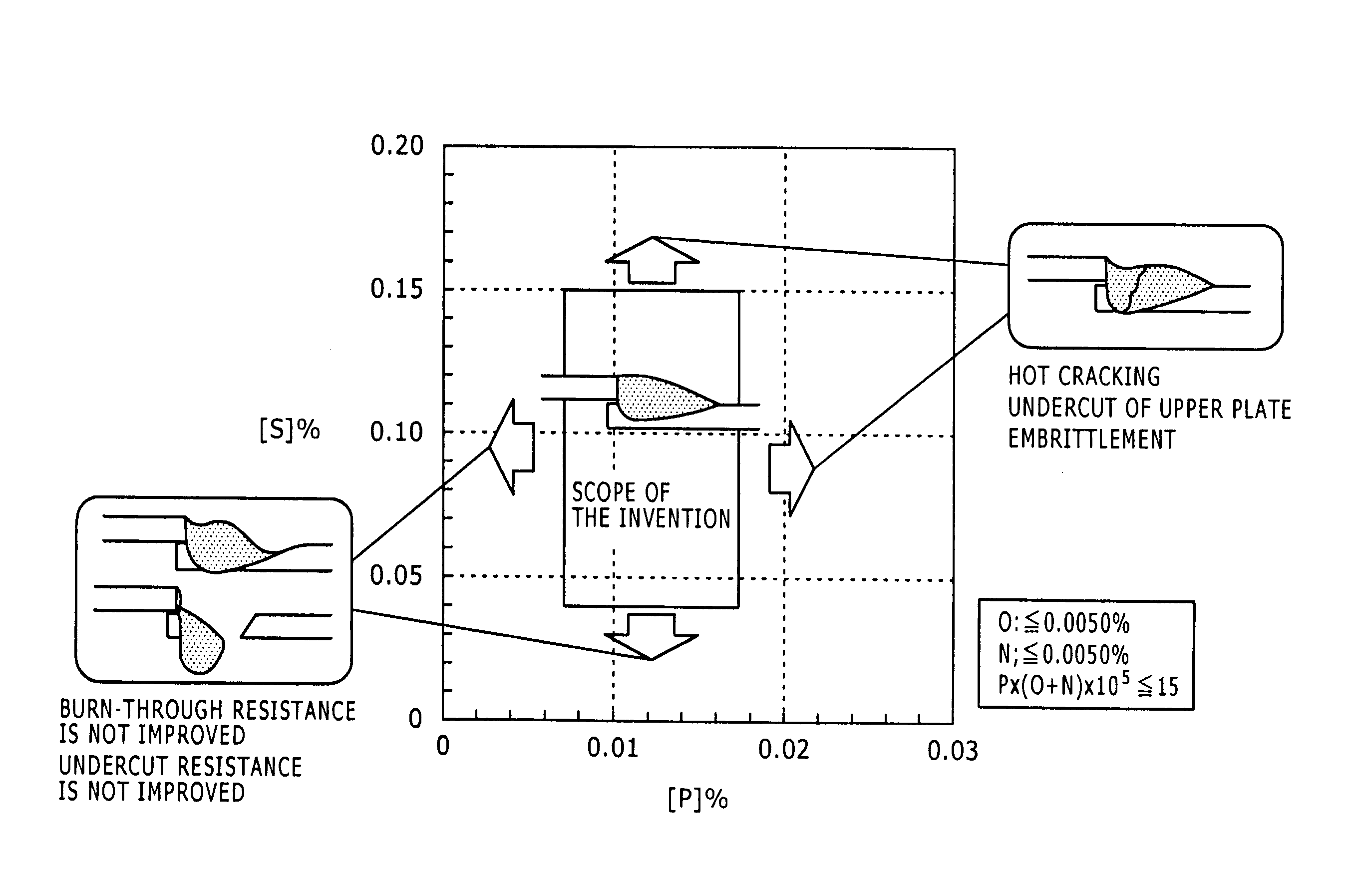
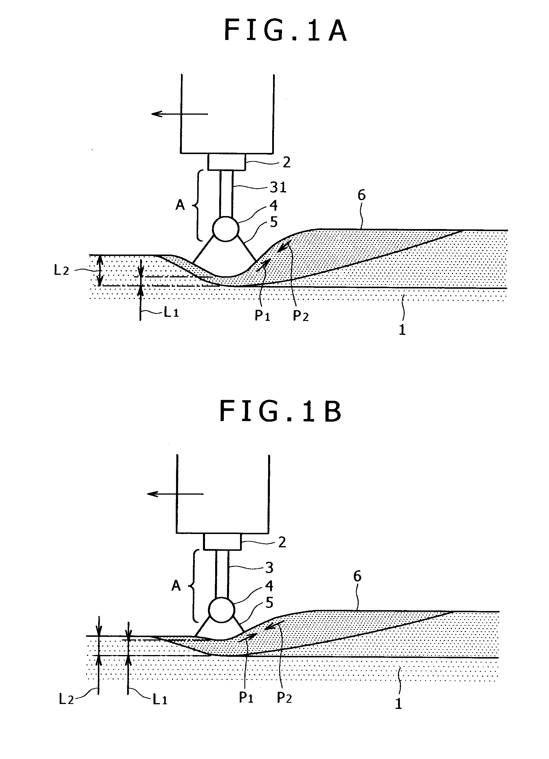
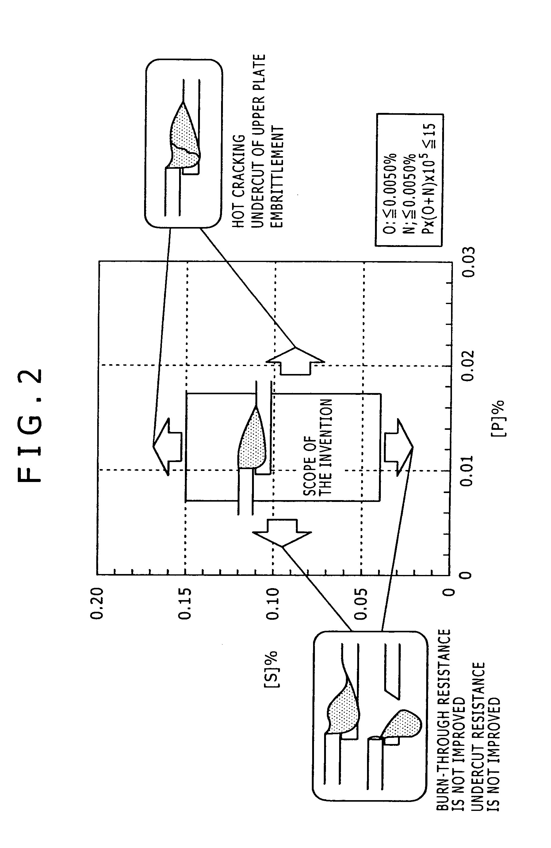
[0018]In the solid wire according to an embodiment of the invention, the content of each of C, Si, Mn, P and S is limited within a particular range, thereby viscosity and surface tension of a molten pool can be significantly decreased, and consequently the molten pool can be formed deep during arc welding. Thus, since a barrier effect of relieving arc force can be obtained, and thus depth of penetration can be decreased, burn-through resistance can be improved.
[0029]The solid wire according to an embodiment of the invention is covered with plated copper, which can improve stain resistance, wear resistance of a current supply tip, and drawability in wire production, and can provide improvement in productivity due to an effect of the improved drawability, and reduction in cost associated with the improved productivity.

Problems solved by technology

However, when the amount of the element to be added into the steel sheet is increased, viscosity of a molten pool during arc welding is increased, thereby blendability is degraded and a weld toe is lose in thickness, so-called undercut tends to occur.
Furthermore, in a point of welding procedure, when welding speed is increased to improve efficiency of welding, arc precedes the molten pool, and thus arc tends to directly impinge upon a molten surface, so that burn through easily occurs.
Even if burn through is not brought, when melting reaches to a back of the sheet material (this is sometimes called penetration welding), hot cracking is induced extremely easily.
While it is previously experientially known that the burn-through resistance and the undercut resistance can be improved by vertical, downward welding, there is a difficulty that a welding position is limited, in addition, when a downward angle is excessively large, welding is hard to be controlled since drop of a bead may occur, or a large amount of spatter may be produced.
However, the wire having a small diameter as described in JP-A-2001-96392 tends to buckle due to the small diameter, and has a difficulty that weldability is degraded since stability of wire feed is bad.
Moreover, there is a difficulty that such a wire small in diameter causes increase in cost, leading to increase in welding cost.
Moreover, the difficulty of bad burn-through resistance cannot be overcome only by using a simple wire as described in specification of Japanese Patent No. 2922814.
Furthermore, there is a difficulty that when the ratio of Ar is increased in shielding gas in such a way, cost of the shielding gas is increased, leading to increase in welding cost.
On the other hand, use of the special welding power supply tip as described in JP-A-9-94667 and specification of Japanese Patent No. 3345883 increases tip cost, leading to increase in welding cost.
In the arc welding method described in JP-A-2005-254284, there is a difficulty that since the special shielding gas is used, cost of the shielding gas is increased, leading to increase in welding cost.
In addition, since a large amount of oxygen is mixed, a large amount of slag or spatter is produced.
The slag or spatter leads to degradation in painting adaptability of a weld.
Furthermore, there is a difficulty that as the amount of oxygen contained in weld metal is significantly increased, inclusions are increased, consequently hot cracking tends to be induced (that is, crack resistance is bad).

Method used


Image

  • Solid wire
  • Solid wire
  • Solid wire

Examples


examples

[0089]Next, regarding the solid wire of an embodiment of the invention, examples that satisfy requirements of an embodiment of the invention and comparative examples that do not satisfy the requirements of an embodiment of the invention are described in detail in contrast with each other.

[0090]Ingot steel having each of compositions shown in Tables 1 to 3 was ingoted by an electric furnace, then the ingot steel was subjected to extrusion rolling and cold drawing so that a welding wire 5.5 mm in diameter was manufactured, and then the welding wire was drawn into a wire having a diameter of 2.4 mm, and the drawn wire was subjected to intermediate annealing and copper plating treatment as necessary for intermediate drawing, and furthermore subjected to finish drawing, and then the drawn wire was subjected to skin-pass and coated with lubricating oil, and consequently a solid wire having a final wire diameter of 1.2 mm was manufactured. K, Li, Na and Ca were contained in a solid lubrica...


PUM

PropertyMeasurementUnit
tensile strengthaaaaaaaaaa
diameteraaaaaaaaaa

Abstract

A solid wire contains C of 0.020 to 0.100 mass percent, Si of 0.25 to 1.10 mass percent, Mn of 1.20 to 1.65 mass percent, P of 0.008 to 0.017 mass percent, S of 0.045 to 0.150 mass percent, O of 0.0050 mass percent or less, N of 0.0050 mass percent or less, wherein P*(O+N)*105≦15 is satisfied, and the remainder including Fe and impurities, wherein the relevant impurities contain Ti of 0.15 mass percent or less, B of 0.0050 mass percent or less, and Cr, Ni, Al, Nb, V, Zr, La and Ce of 0.20 mass percent or less respectively. According to such a configuration, a solid wire is provided, in which while increase in welding cost is controlled to the minimum, stability of wire feed, burn-through resistance, undercut resistance, and crack resistance are excellent, slag and spatter are hardly produced, hardness of weld metal is equal to or higher than that of base metal, and brittle fracture hardly occurs.

Description

BACKGROUND OF THE INVENTION[0001]The present invention relates to a solid wire used for arc welding, and particularly relates to a solid wire for carbon steel usable for arc welding of a sheet.DESCRIPTION OF RELATED ART[0002]Recently, improvement in fuel consumption of a car is increasingly demanded in the light of the environmental issue. To response to this, change of a steel sheet to be used is progressively tried from usual mild steel having a tensile strength of 300 MPa or less to a high strength steel sheet having a tensile strength of 400 MPa or more so that sheet thickness is reduced to achieve lightweight.[0003]Here, when sheet thickness is reduced, while substantially no difficulty is found in spot welding, a phenomenon that a steel sheet is locally melted due to arc heat, and eventually a hole is opened, so-called burn through easily occurs in arc welding.[0004]Increase in strength of a steel sheet is typically achieved by cooling control during rolling, and increasing th...

Claims


Application Information

Patent Timeline
Patent Type & Authority Applications(United States)
IPC IPC(8): B23K35/24
CPCB23K35/3053B23K35/0261C22C38/04B23K35/404
Inventor SUZUKI, REIICHIUMEHARA, YU
Owner KOBE STEEL LTD
Learn More