Wall flow reactor for hydrogen production

a wall flow reactor and hydrogen gas technology, applied in the direction of chemistry apparatus and processes, liquid chemical processes, chemical/physical/physical-chemical processes, etc., can solve the problems of difficult to maintain the position-fixed position of staged thin layers of catalysts, difficult to couplate endothermic and exothermic reactions, and high cost of hydrogen gas production. , to achieve the effect of reducing the co content, maximizing the amount of h2 and co production

Inactive Publication Date: 2008-06-12
CORNING INC
View PDF18 Cites 17 Cited by
  • Summary
  • Abstract
  • Description
  • Claims
  • Application Information

AI Technical Summary

Benefits of technology

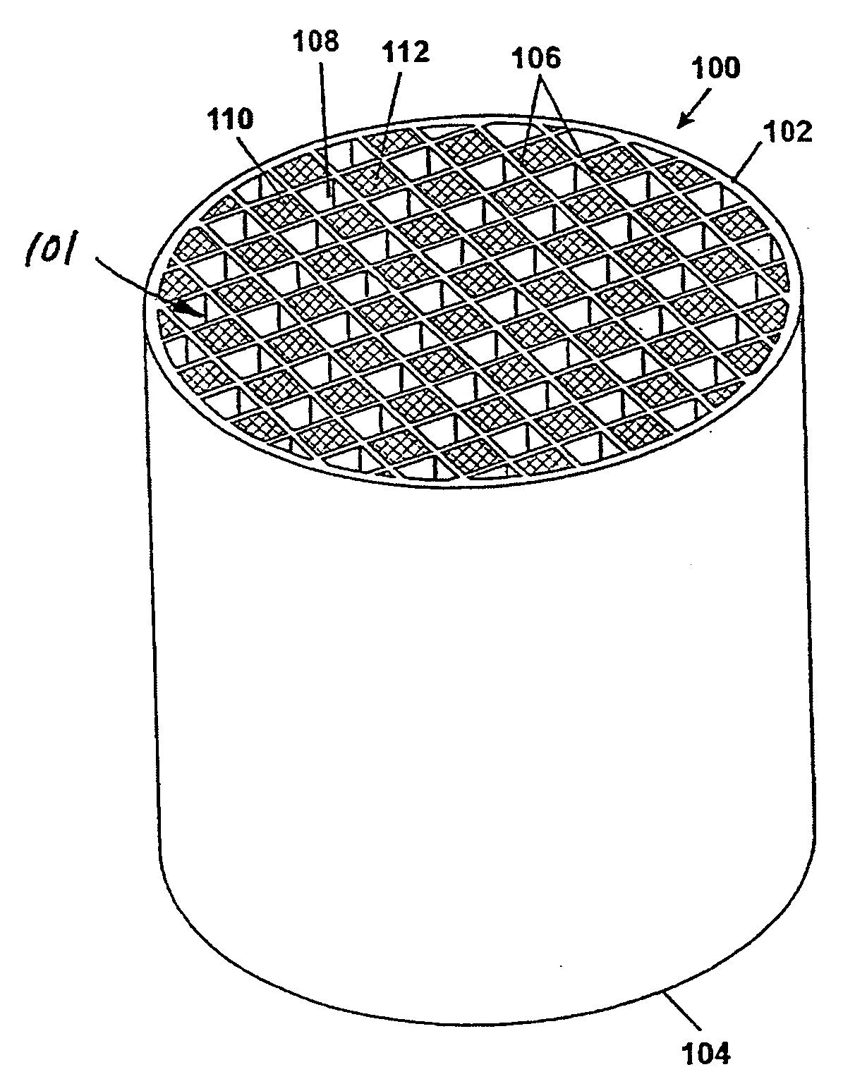
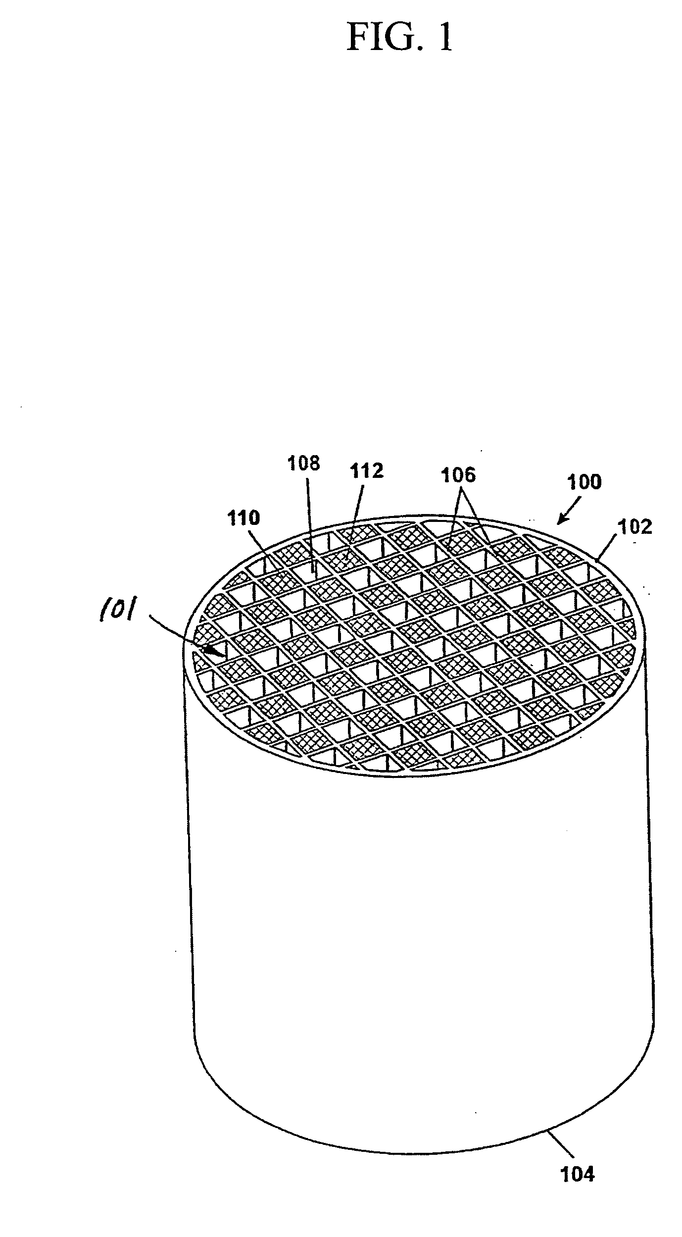
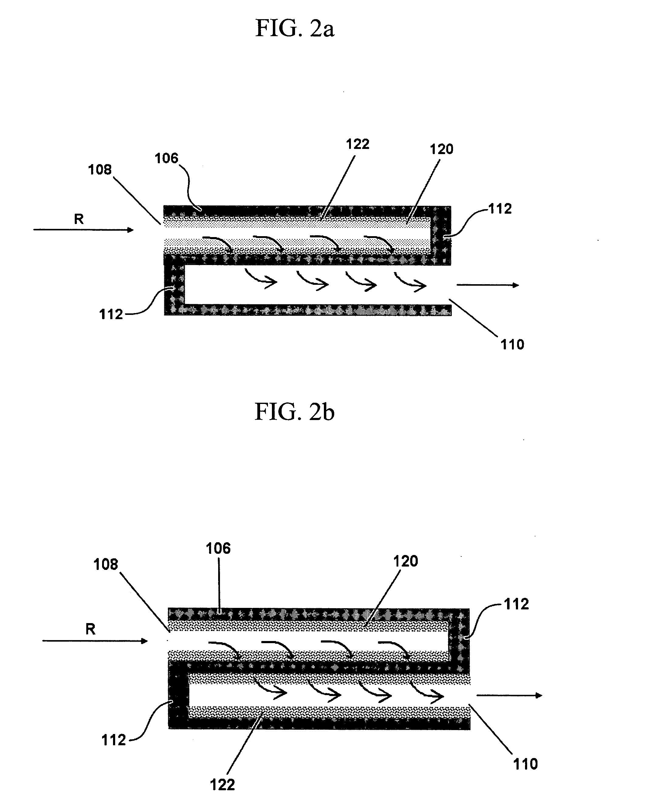
[0011]The present invention provides a wall flow reactor which enables the staging of multiple thin catalyst layers in a manner that at least substantially eliminates the problems associated with conventional devices and processes described above. For example, by staging the multiple thin washcoat layers on a porous monolithic honeycomb substrate walls, it is possible to internally couple exothermic and endothermic reaction in such a way that the exothermic methane oxidation occurs on the one catalyst layer with CO, CO2 and H2O produced as main products. Those products, together with excess methane passing to the second catalyst layer which has desired endothermic methane reforming function, can result in a relatively high ratio of H2 and CO production. If desired, these H2-rich product streams can further pass in contact with a Water-Gas-Shift catalyst layer to maximize even more H2 production and even lower the CO content. One can pursue this embodiment by sequentially staging multiple thin layer washcoat catalysts.

Problems solved by technology

However, the expense associated with this process is typically up to four times more expensive than the cost of gasoline.
Coupling these endothermic and exothermic reactions is very difficult using conventional granular type catalyst fixed-beds as it is very difficult to maintain staged thin layers of catalysts position-fixed all time.
Similarly, use of the foam monoliths described above makes it very difficult to machine the bulk monolith into a very short monolith layer (few millimeters to few center meters), especially when the diameter of the monolith is relatively large Further, it is also challenging to make an active catalyst deposition on a “pan-cake” shaped foam monolith uniform.
With respect to catalyst and reactor scale up, it is also quite challenging to manufacture a relatively large diameter reactor (e.g., D˜1.0 m) with multiple layers of different catalysts (layer thickness˜few cm) and with very short reactor length.
In particular, one cannot simply increase the layer thickness because of the limitation of the total pressure-drop especially when the small granular catalysts are used.
Thus, to make the entry flow a uniform distribution is another challenge especially for such a large diameter pan-cake shaped reactor.
Still further, adding too many inert layers for better flow distribution often ends up with high pressure-drop increase.
Because of the limitation of big reactor diameter and limitation of using thick packing layers, one has to increase the number of “pan-cake” type reactors to meet certain productivity needs, which will increase both capital and operational costs of the process.

Method used


Image

  • Wall flow reactor for hydrogen production
  • Wall flow reactor for hydrogen production
  • Wall flow reactor for hydrogen production

Examples


Embodiment Construction

[0022]The following description of the invention is provided as an enabling teaching of the invention in its best, currently known embodiment. To this end, those skilled in the relevant art will recognize and appreciate that many changes can be made to the various embodiments of the invention described herein, while still obtaining the beneficial results of the present invention. It will also be apparent that some of the desired benefits of the present invention can be obtained by selecting some of the features of the present invention without utilizing other features. Accordingly, those who work in the art will recognize that many modifications and adaptations to the present invention are possible and can even be desirable in certain circumstances and are a part of the present invention. Thus, the following description is provided as illustrative of the principles of the present invention and not in limitation thereof.

[0023]As used herein, the singular forms “a,”“an” and “the” incl...


PUM

PropertyMeasurementUnit
thicknessaaaaaaaaaa
depthaaaaaaaaaa
total porosityaaaaaaaaaa

Abstract

Disclosed herein are wall flow reactors that are suitable for the production of hydrogen gas from hydrocarbon and/or its derivative feed streams. The wall flow reactors are generally comprised a monolithic honeycomb substrate defining a plurality of cell channels bounded by porous channel walls that extend longitudinally from an upstream inlet end to a downstream outlet end; wherein a first portion of the plurality of cell channels are plugged at the downstream outlet end to form inlet cell channels and a second portion of the plurality of cell channels are plugged at the upstream inlet end to form outlet cell channels. A plurality of catalyst layers are positioned within at least a portion of the plurality of cell channels and comprise at least a first catalyst layer and a second catalyst layer. Also disclosed are methods for treating reactant feed streams.

Description

BACKGROUND OF THE INVENTION[0001]1. Field of the Invention[0002]The present invention relates to a process and apparatus for the production of hydrogen gas from a hydrocarbon and / or its derivative feed streams.[0003]2. Technical Background[0004]Much interest has recently been directed to hydrogen gas (H2) as U.S. Administration's future fuel of choice. In particular, hydrogen fuel is now required for use in many energy related processes. For example, hydrogen fuel cells represent an exemplary energy related application that has received increased attention in recent years as a possible substitute for energy dependency on gasoline and related non-renewable fossil fuels. To this end, hydrogen can for example be produced by cracking natural gas. However, the expense associated with this process is typically up to four times more expensive than the cost of gasoline. Therefore, to make H2 a more widely available commodity, it is necessary to develop more efficient high-throughput H2 prod...

Claims


Application Information

Patent Timeline
Patent Type & Authority Applications(United States)
IPC IPC(8): C01B3/02B01J16/00
CPCB01J12/007C01B2203/1076B01J19/2485B01J2208/021C01B3/382C01B3/48C01B2203/0233C01B2203/0244C01B2203/0261C01B2203/0283C01B2203/0844C01B2203/1023C01B2203/1035C01B2203/1041C01B2203/1047C01B2203/1052C01B2203/1058C01B2203/107B01J19/2475
Inventor JIANG, YI
Owner CORNING INC
Why Eureka
Try Eureka