Tunnel magnetoresistance effect device, and a portable personal device

a technology of tunnel magnetoresistance and effect device, which is applied in the field of tunnel magnetoresistance effect device and portable personal device, can solve the problems of affecting the fixing of magnetization, affecting the magnetoresistivity ratio of tmr device, and not being able to prevent the diffusion of mn into the tunnel barrier layer

Inactive Publication Date: 2008-06-19
TOSHIBA MEMORY CORP
View PDF22 Cites 11 Cited by
  • Summary
  • Abstract
  • Description
  • Claims
  • Application Information

AI Technical Summary

Benefits of technology

[0018]An object of the present invention is to provide a tunnel magnetoresistance effect device (TMR device) that is capable of effectively suppressing the diffusion of Mn from the antiferromagnetic material layer made of a Mn-based alloy into the tunnel barrier layer even in case of heat treatment, and yet, which exhibits superior device characteristics and thermal stability. Another object of the present invention is to provide a portable personal device equipped with such a TMR device.
[0025]In accordance with the invention as above, the diffusion of Mn from the antiferromagnetic material layer made of a Mn-based alloy into the tunnel barrier layer, even in case of heat treatment, can be effectively suppressed, and hence, a TMR device having superior device characteristics and thermal stability can be provided.

Problems solved by technology

The diffused Mn then lowers the spin polarization ratio of the magnetization fixed ratio 102 and leads to a problematic decrease in magnetoresistivity ratio of the TMR device.
However, as a result of the studies of the present inventors, it has been found that the metallic elements above cause grain boundary diffusion of Mn at temperatures of 300° C. or higher, and that it is not possible to prevent the diffusion of Mn from occurring into the tunnel barrier layer.
However, as a result of the studies of the present inventors, it has been found that a refractory metal layer provided at the interface between the antiferromagnetic material layer 101 and the magnetization fixed layer 102 not only greatly impairs the fixing of the magnetization of the fixed layer 102, but also raises a concern that the refractory metal itself undergoes diffusion.

Method used


Image

  • Tunnel magnetoresistance effect device, and a portable personal device
  • Tunnel magnetoresistance effect device, and a portable personal device
  • Tunnel magnetoresistance effect device, and a portable personal device

Examples


first embodiment

of the Present Invention

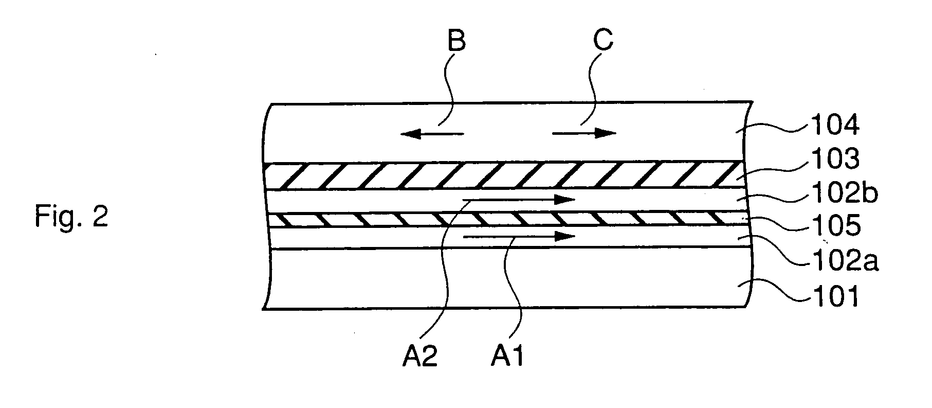
[0037]FIG. 2 shows a cross section view of a TMR device according to a first embodiment of the present invention.

[0038]Referring to FIG. 2, the TMR device according to the first embodiment comprises an antiferromagnetic material layer 101 made of an antiferromagnetic material, a first magnetization fixed layer 102a made of a ferromagnetic material, an insulator material layer 105, a second magnetization fixed layer 102b made of a ferromagnetic material, a tunnel barrier layer 103 made of an insulator material, and a magnetization free layer 104 made of a ferromagnetic material.

[0039]Each of the layers above is laminated sequentially on a substrate not shown. Furthermore, the order of laminating the layers on a substrate as shown in the structure of FIG. 2 may be reversed. Additionally, the preposition “on” used in this specification and the appended claims does not exclude intervening layers unless “direct contact” is specified.

[0040]For the antiferromagnetic...

second embodiment

of the Present Invention

[0059]FIGS. 3A, 3B, and 3C are each a cross section view provided as explanatory means for describing the TMR device and the fabrication process thereof according to a second embodiment of the present invention.

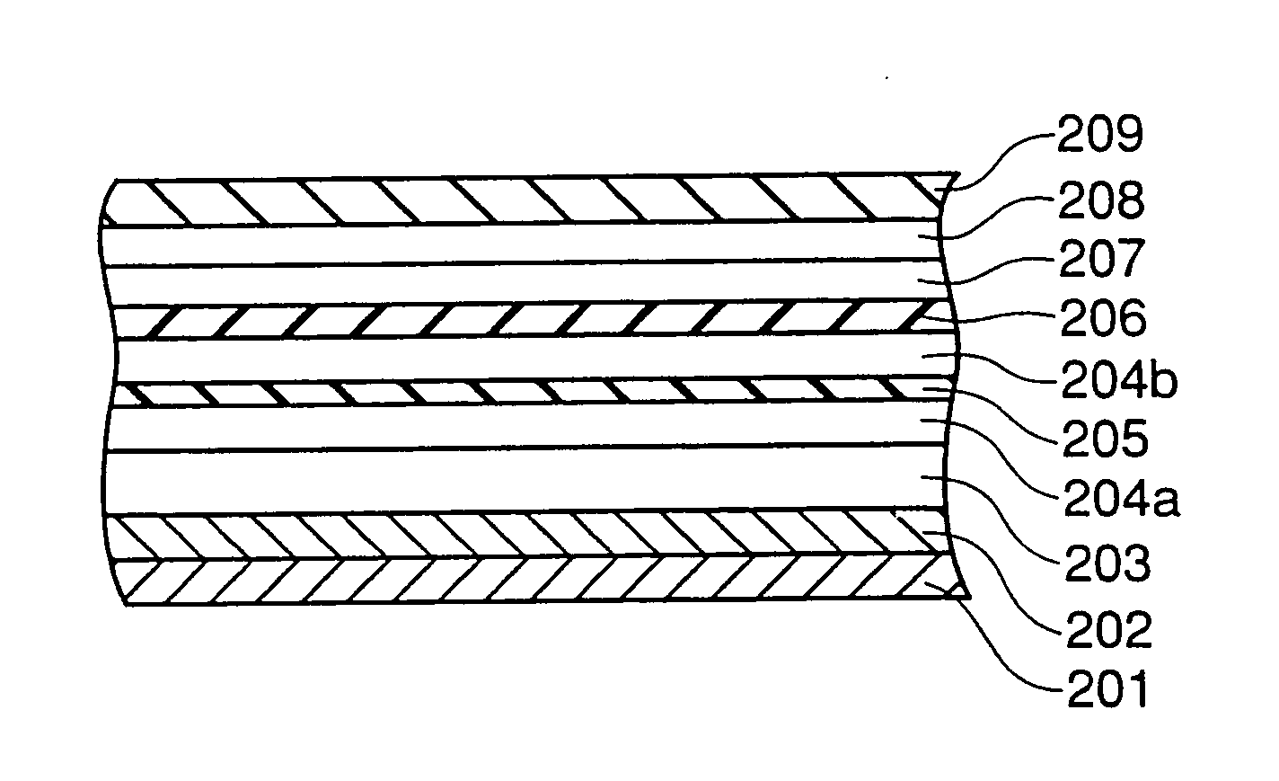
[0060]Referring to FIG. 3C, the TMR device according to a second embodiment of the present invention comprises a buffer layer 202 made of Ta or the like comprising disposed thereon an antiferromagnetic layer 203 made of an antiferromagnetic material, a first and a second magnetization fixed layer 204a and 204b, an insulator material layer 205 made of an insulator material, a tunnel barrier layer 206 made of a non-magnetic dielectric material, a magnetization free layer 207, a soft magnetic layer 208 made of NiFe, etc., which causes the soft magnetization of the magnetization free layer 207, and a protective layer 209 made of Ta, etc.

[0061]A lower interconnection electrode layer 201 is formed below the antiferromagnetic material layer 203 with a buffer ...

third embodiment

of the Present Invention

[0079]FIGS. 4A, 4B, 4C, and 4D are each a cross section view provided as explanatory means for describing the TMR device and the fabrication process thereof according to a third embodiment of the present invention.

[0080]Referring to FIG. 4D, the TMR device is a dual spin valve TMR device having a double tunnel junction, comprising two magnetization fixed films on the upper and the lower sides of a magnetization free layer 307 via a first and a second tunnel barrier layer 306 and 308 disposed on the upper and the lower sides thereof.

[0081]The lower magnetization fixed film is provided with a first magnetization fixed layer 304a, a first insulator material layer 305, and a second magnetization fixed layer 304b, and the upper magnetization fixed film is provided with a third magnetization fixed layer 309a, a second insulator material layer 310, and a fourth magnetization fixed layer 309b.

[0082]The magnetization of the first magnetization fixed layer 304a is fix...


PUM

PropertyMeasurementUnit
thicknessaaaaaaaaaa
thicknessaaaaaaaaaa
temperatureaaaaaaaaaa

Abstract

A TMR device comprising an antiferromagnetic layer made of an antiferromagnetic material containing Mn, a magnetization fixed layer made of a ferromagnetic material, a tunnel barrier layer made of a dielectric material, and a magnetization free layer made of a ferromagnetic material. An insulator material layer is inserted in the magnetization fixed layer at a distance from the antiferromagnetic material layer and the tunnel barrier layer. One material can be expressed by NX, where X is a first element selected from the group consisting of oxygen, nitrogen and carbon; and N is a second element, provided that the bonding energy between the first and the second elements is higher than the bonding energy between manganese and the first element. A second material can be expressed by MX, where M is an element selected from the group consisting of titanium, tantalum, vanadium, aluminum, europium, and scandium; and X is an element selected from the group consisting of oxygen, nitrogen and carbon. The tunnel magnetoresistance effect device suppresses the diffusion of Mn from the Mn based alloy constituting the antiferromagnetic material layer even after heat treatment is performed.

Description

CROSS-REFERENCE TO RELATED APPLICATIONS[0001]This application is a continuation of U.S. application Ser. No. 10 / 884,946, filed Jul. 7, 2004 and claims priority to Japanese Patent Application No. 2000-275030, filed on Sep. 11, 2000 and Japanese Patent Application No. 2001-212595 filed Jul. 12, 2001; which is a continuation of U.S. application Ser. No. 09 / 944,044 which was filed Sep. 4, 2001, the entire contents of which are incorporated herein by reference.BACKGROUND OF THE INVENTION[0002]1. Field of the Inventions[0003]The present invention relates to a tunnel magnetoresistance effect device and to a portable personal device having a magnetic memory provided with said tunnel magnetoresistance effect device.[0004]2. Discussion of the Background[0005]A magnetoresistance effect element using a ferromagnetic thin film is used in, for instance, a magnetic head, a magnetic sensor, etc. Furthermore, a magnetic random access memory (MRAM) is recently proposed, which comprises a semiconducto...

Claims


Application Information

Patent Timeline
Patent Type & Authority Applications(United States)
IPC IPC(8): G11B5/33G11B5/39G01R33/09G11C11/15H01F10/16H01F10/187H01F10/32H01L21/8246H01L27/105H01L27/22H01L43/08H01L43/12
CPCB82Y10/00B82Y25/00G01R33/093G01R33/098G11B5/3906H01L43/08G11C11/15H01F10/3254H01F10/3268H01F10/3272H01L27/228G11B5/3909H10B61/22H10N50/10G11B5/39
Inventor AMANO, MINORUSAITO, YOSHIAKI
Owner TOSHIBA MEMORY CORP
Why Eureka
Try Eureka