Integrated Thermoelectric/ Thermionic Energy Converter

a technology of thermionic energy converter and integrated technology, which is applied in the direction of electrical equipment, generators/motors, electric discharge tubes, etc., can solve the problems of reducing performance, thermionic energy converter, and both types of devices have limitations, so as to improve the thermal efficiency of tite converter and reduce heat rejection temperature , the effect of double the output voltage of tite converter

Inactive Publication Date: 2008-08-21
RASOR NED S +1
View PDF11 Cites 11 Cited by
  • Summary
  • Abstract
  • Description
  • Claims
  • Application Information

AI Technical Summary

Benefits of technology

[0012]In the TITE device, hot electrons from the emitter or plasma in a thermionic discharge are collected by an appropriately selected semiconductor or undoped semiconductor material layer on the metal collector electrode. The electron current and energy output from the thermionic region of the interelectrode space becomes the electron current and energy input to the thermoelectric region. The result is a more than doubled output voltage of the TITE converter over that of most conventional thermionic converters because of the lowered heat rejection temperature

Problems solved by technology

However, both types of devices have limitations which reduce performance.
Another basic performance limitation in thermionic energy converters is excessive electron energy loss at the collector.
Also, the electrons lose even more potential energy as they are collected across the potential energy barrier at the collector.
Because the lowest work function practically available is greater than φC˜1.4 eV, the output voltage of the converter is greatly reduced and low temperature heat rejection cannot be effectively used.
The electrical and thermal performance of thermoelectric energy conversion also is limited primarily by two physical processes.
This means that

Method used


Image

  • Integrated Thermoelectric/ Thermionic Energy Converter
  • Integrated Thermoelectric/ Thermionic Energy Converter
  • Integrated Thermoelectric/ Thermionic Energy Converter

Examples


Embodiment Construction

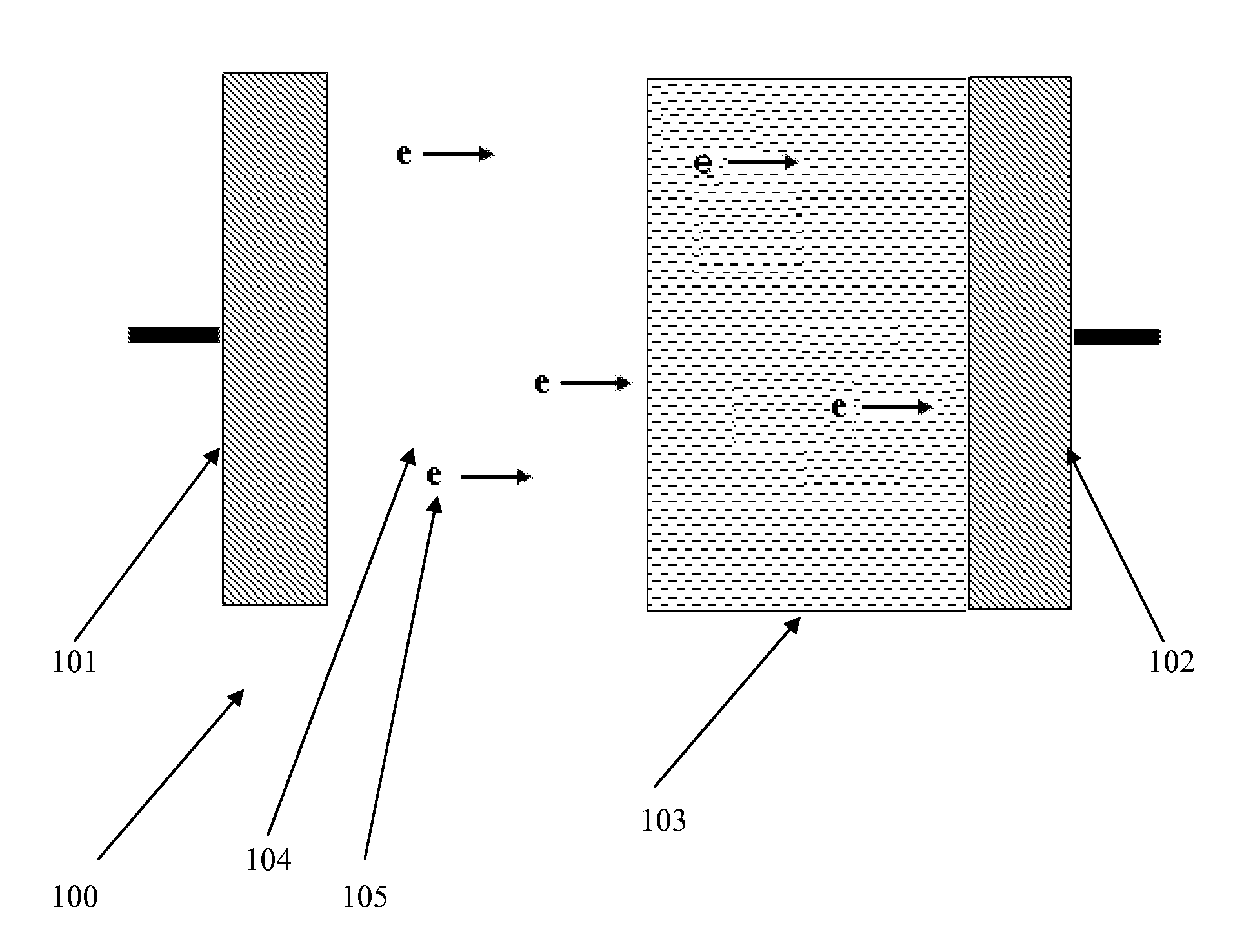
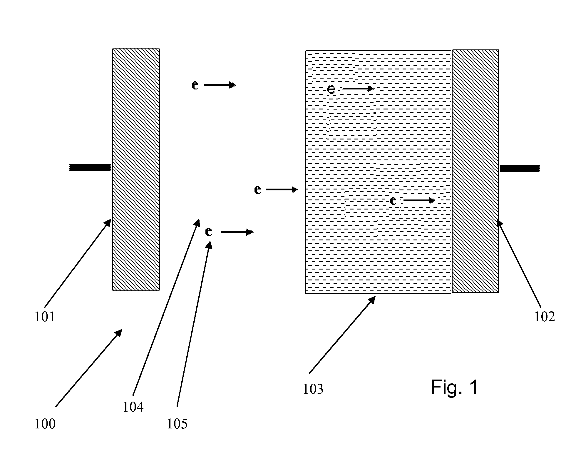
[0027]In its most basic form, with reference to FIGS. 1 and 2, the TITE device 100 comprises an emitter 101, a metallic collector 102, and a semiconductor coating 103 on the collector 102. The emitter 101 is separated from the semiconductor—or, alternatively, an undoped semiconductor material layer—coating 103 by a gap 104 comprising either a vacuum (including quasi-vacuum, as described below) or plasma. As in current thermionic devices, cesium vapor, which is the most easily ionized of all the stable elements, can be used in the gap 104 in the plasma or quasi-vacuum. The gap 104 is generally on the order of 105 are emitted by the emitter 101, move across the vacuum or plasma gap 104, and are injected at high potential energy directly into the semiconductor or undoped semiconductor material coating 103 layer for thermoelectric conversion of their energy into additional electric power at the collector 102. Effectively, then, the electron current and energy output from the thermionic ...


PUM


Abstract

A device for converting heat into electrical energy that is an integrated combination of thermionic and thermoelectric energy converters in a single device, or “TITE”. The electron output of thermionic portion of the TITE is the input of the thermoelectric portion of the device. The electron collector is covered by a thin layer of doped or undoped semiconductor material or a combination of doped and undoped semiconductor materials with appropriate doping and thickness to achieve increased operational temperature ranges and efficiency.

Description

CROSS-REFERENCE TO RELATED APPLICATIONS[0001]This invention is a continuation-in-part of provisional patent applications 60 / 815,757 and 60 / 848,795 which are incorporated by reference herein.BACKGROUND OF THE INVENTION[0002]The invention relates to an integrated combination of thermionic energy conversion and thermoelectric energy conversion in a single device. The integrated thermionic / thermoelectric physical process and device are designated by the name “TITE.”[0003]A thermionic energy converter is a gaseous electronic device by which heat is converted directly into electric power non-mechanically by thermionic emission or evaporation of electrons from a hot electrode or emitter and their collection or condensation in a colder electrode or collector. A thermoelectric energy converter, or thermocouple, is a solid state device by which heat is converted into electric power by diffusion of electrons and holes down a temperature gradient, and up a potential gradient, in series-connecte...

Claims


Application Information

Patent Timeline
IPC IPC(8): H02N11/00
CPCH01L35/00H01J45/00H10N10/00
Inventor RASOR, NED S.HANSEN, LORIN K.
Owner RASOR NED S
Why Eureka
Try Eureka