Plasma Centrifuge Heat Engine Beam Fusion Reactor

a technology of fusion reactor and centrifuge, which is applied in nuclear reactors, nuclear engineering, greenhouse gas reduction, etc., can solve the problems of low reactivity and associated power density, unable to withstand energetic neutrons, and known processes for fusion energy release require extreme conditions, so as to reduce the temperature of plasma, increase the density, and increase the power density

Inactive Publication Date: 2008-09-18
BARNES DANIEL C
View PDF0 Cites 59 Cited by
  • Summary
  • Abstract
  • Description
  • Claims
  • Application Information

AI Technical Summary

Benefits of technology

[0014]In comparison with thermonuclear fusion systems, required plasma temperature is reduced by over a factor of 10. For the same confined pressure, this leads to an increase in density by over a factor of 10 and an increase in power density by over a factor of 100. Increased reactivity also accrues from operation at an optimal beam energy. These combined advantages reduce the required volume of the fusion reactor by about 1000 times. Deuterium-tritium systems become very compact and inexpensive, in comparison with thermonuclear systems. Proton-Boron-11 systems become competitive with deuterium-tritium thermonuclear systems in size and power density, offering the large advantages of operation of a fusion reactor without neutron production.
[0015]All embodiments share these common features: 1) a plasma is formed in an evacuated chamber and confined by a magnetic field generated by a combination of external coils and plasma currents; 2) the magnetic configuration is static and nearly or exactly symmetric with respect to rotation about an axis of cylindrical symmetry; 3) the magnetic field lies within planes which contain this axis, forming “closed” or “open” field lines, which lines of force are tangent to the direction of the magnetic field; 4) plasma confined on these closed and open field lines is caused to rotate by a combination of applied electrical potentials and the conversion of plasma heat to rotation; 5) a key feature is the aforesaid region of open field lines which surround any closed field line region and connect from the structure at one end to that at the opposite end of the machine, and the variation of the radius (distance from the axis) of said open field lines along their length; 6) said radius increases from a small value near the ends of the machine to a large value near the middle of the machine, trapping plasma by centrifugal force; 7) the strength of the magnetic field is engineered to increase from a value near zero near the ends to a maximum value of 1 to several Tesla near the middle of the machine; and 8) conversion of plasma heat to rotation occurs by the Coriolis effect as plasma moves along the open field lines and either escapes or cools near the small radius regions at the ends of the machine. Another key feature is the use of static magnetic perturbations to induce waves in the plasma. The plasma rotation converts these static fields into plasma waves which are used to drive plasma currents or to accelerate particles to produce th

Problems solved by technology

On the other hand, known processes for the release of fusion energy require extreme conditions.
The containment of such extreme temperatures at practical pressures, and with sufficient quality of confinement has posed a challenge for more than the past ½ century.
Additionally, an aneutronic fusion system may be engineered so that it can not withstand energetic neutrons.
The increased temperature implies reduced density at the same pressure achieved, leading to very low reactivity and associated power density.
A combination of all these factors implies that a thermonuclear proton-Boron-11 system, if it could work at all, would have a volume of about 1000 times the present deuterium-tritium tokamak systems, rendering such an embodiment impractically expensive and complex.
All of these past schemes for beam-target fusion have suffered from the difficulty of parasitic l

Method used


Image

  • Plasma Centrifuge Heat Engine Beam Fusion Reactor
  • Plasma Centrifuge Heat Engine Beam Fusion Reactor
  • Plasma Centrifuge Heat Engine Beam Fusion Reactor

Examples


Embodiment Construction

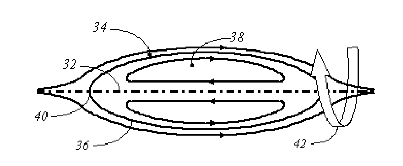
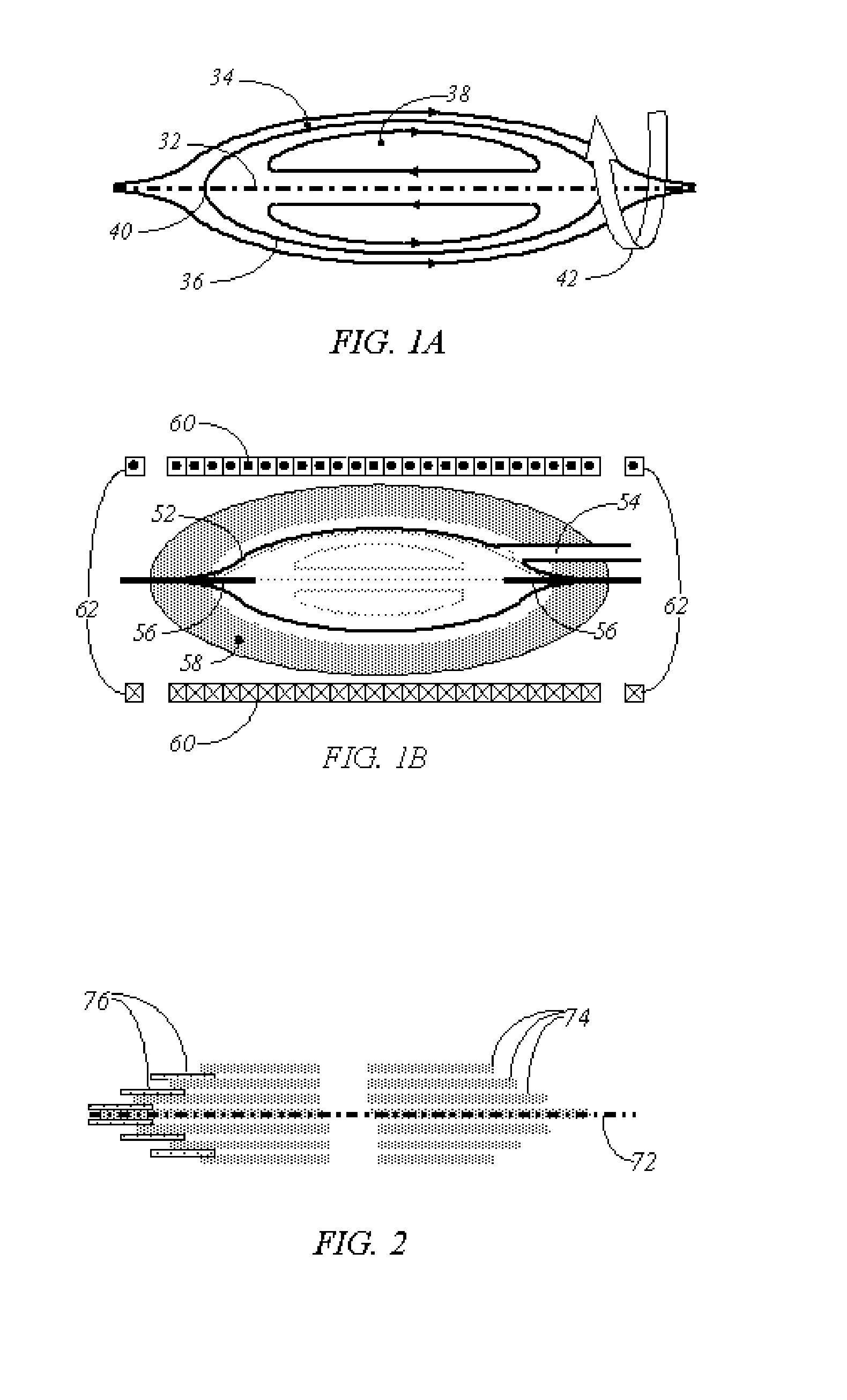
[0033]A first preferred embodiment accomplishes a heat engine cycle in a continuous plasma state. The required open field line magnetic configuration is produced by a field-reversed configuration. The magnetic configuration for this case is as shown in FIG. 1A. Since the entire system is rotationally symmetric, arrangement and operation is shown entirely by sections which correspond to cuts through a plane that contains the system axis. The axis of symmetry 32 forms the centerline of the system. An open field region 34 is separated from a closed field region 38 by the separatrix 36. The open field lines of interest are those which pass very close to the axis near points 40 on the axis at either end of the configuration where the magnetic field vanishes (spindle cusp points). The direction of the magnetic field is indicated along various field lines, while the direction of rotation is shown by the heavy arrow 42. Open-field-line plasma is continuously confined by centrifugal force, w...


PUM


Abstract

A system and apparatus for a magnetized plasma nuclear fusion reactor, incorporating special design features which induce a plasma heat engine cycle in a rapidly rotating plasma. The heat engine operates either continuously or by oscillations. A continuous heat engine is formed in the open field outside a field reversed configuration. The oscillatory system operates in synchronism with cyclic acceleration, collision, and deceleration of plasma masses to produce nuclear fusion reactions at an economically useful rate with a relatively small driving power required. A special magnetic field design is combined with applied electrical voltages at the end of the field lines to produce required conditions. Design features allow recovery of large fraction of collision heat which would otherwise be dissipated as a parasitic loss.

Description

CROSS-REFERENCE TO RELATED APPLICATIONS[0001]This application is a continuation of provisional application 60 / 596,567, “Plasma Centrifuge Heat Engine for Colliding Beam Fusion Applications”, filed Oct. 4, 2005 and provisional application 60 / 766,791, “Plasma Centrifuge Heat Engine for Continuous Beam Fusion Reactor”, filed Feb. 12, 2006, which applications are fully incorporated herein by reference.BACKGROUND OF THE INVENTIONField[0002]This invention is in the fields of plasma physics and energy supply and provides a new basis for operation of nuclear fusion reactor systems.[0003]Nuclear fusion is a process which can produce virtually unlimited energy from plentiful and inexpensive fuel. For example, the fusion yield of a single gram (about the mass of a postage stamp) of deuterium-tritium (isotopes of hydrogen which are easily and inexpensively obtained) mixed in equal proportions is about 352 giga-Joules of energy, the energy equivalent of over 3000 gallons of gasoline. On the othe...

Claims


Application Information

Patent Timeline
IPC IPC(8): G21B1/03
CPCG21B1/05Y02E30/126Y02E30/122G21B1/052Y02E30/10
Inventor BARNES, DANIEL C.
Owner BARNES DANIEL C
Why Eureka
Try Eureka