Laser Cladding on Low Heat Resistant Substrates

a technology of low heat resistance and substrate, applied in the direction of metal-working equipment, metal-coating process, welding/cutting media/materials, etc., can solve the problems of corrosive gases, tuyeres and nozzle tips of metallurgical vessels, and the presence of hot particle erosion and molten slag or metal attack of lances and nozzles of metalurgical vessels

Inactive Publication Date: 2008-09-18
PRAXAIR ST TECH INC
View PDF4 Cites 63 Cited by
  • Summary
  • Abstract
  • Description
  • Claims
  • Application Information

AI Technical Summary

Benefits of technology

[0017](c) generating sufficient power to the laser to superficially heat said substrate and to effect a fusion bond between the metal, alloy or metal-alloy composite powder and the surface of the substrate. The laser creates superficial heating of said substrate without distortion of said substrate, so as to provide the laser clad layer having the contour as the design shape of said machine component. The substrate is preferably copper or a copper-base alloy.

Problems solved by technology

In addition to these, metallurgical vessels' lances and nozzles typically experience both hot particle erosion and molten slag or metal attack.
An additional problem is the presence of corrosive gases.
These gases aggressively attack metal injection devices.
Yet another problem with coated tuyeres and nozzle tips is cracking after a period of service under extreme cyclic heating and cooling.
This cracking can propagate toward the inner wall, causing eventual water leakage.
Unfortunately, all these materials wear extensively within a short time and often require as frequent as weekly replacement.
The overlay often cracks and separates in service due to molten metal attack.
With a reduced thickness of 0.010 to 0.020″, the coating is lost very rapidly due to the extremely high surface loading coupled with wedging of fine hard dross (iron-zinc-aluminum intermetallic), and the coating provides no significant economic gains.
On the other hand, the thick spray-fuse coatings crack, which leads to interface attack by zinc or aluminum.
Thus, the coating eventually spalls before actually losing the coating through wear.
With PTA weld overlay of cobalt alloys, dilution, while less than the arc welding, still is excessive.

Method used


Image

  • Laser Cladding on Low Heat Resistant Substrates
  • Laser Cladding on Low Heat Resistant Substrates

Examples


example

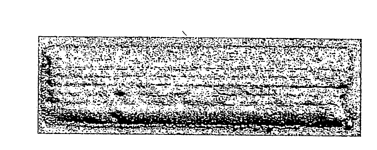
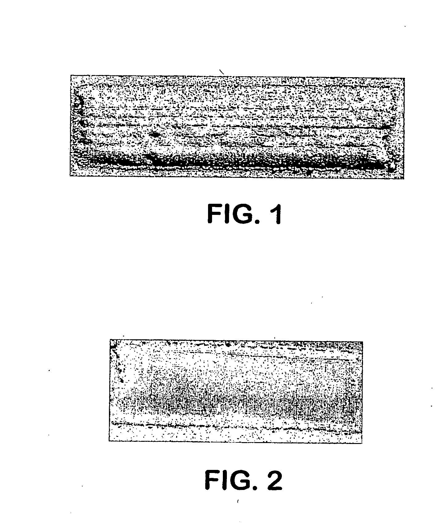
[0076]A laser cladding process was conducted utilizing Nd:YAG laser. The process parameters are set forth below. The coating material was injected into a melt pool. The laser beam was guided over the part surface generating a weld bead. Overlapping the individual weld bead at a certain index produced the clad. The clad layer was then polished. FIG. 1 shows a Nd:YAG laser clad surface of a CoCrC coating applied onto the copper substrate in accordance with this example. FIG. 2 shows a Nd:YAG laser clad and polished surface of a CoCrC coating applied onto the copper substrate in accordance with this example.

Base metal: Copper (Cu)

Coating material: CoCrC alloy

Laser: Nd:YAG, diode pumped, fiber delivered maximum output power of 5 kW

Laser power utilized: 4 kW

Laser spot size: approximately 3 mm diameter

Surface speed: 250-400 mm per minute

Index: 1.5 mm

[0077]Powder feed rate: 6 grams per min.


PUM

PropertyMeasurementUnit
wavelengthsaaaaaaaaaa

Abstract

This invention relates to laser cladding of components used in high temperature-corrosive applications, such as those associated with metallurgical vessels' lances, nozzles and tuyeres, for extending their service life under such severe conditions. In particular, this invention relates to a method for applying a high melting point material onto a substrate, said substrate having a melting point temperature below the melting point temperature of the high melting point material, comprising: (a) moving a laser beam generated from a laser over the surface of said substrate, said laser beam comprised of wavelengths from about 300 to about 10,600 nanometers; (h) providing a metal, alloy, or metal-alloy composite powder to the surface of said substrate; and (c) generating sufficient power to the laser to superficially heat said substrate and to effect a fusion bond between the metal, alloy or metal-alloy composite powder and the surface of said substrate.

Description

FIELD OF THE INVENTION[0001]The invention relates to a method of laser cladding high melting point metals, alloys and / or metal composites onto low heat resistant substrates, such as copper or similar materials. In particular, the invention relates to laser cladding of components used in high temperature-corrosive applications, such as those associated with metallurgical vessels' lances, nozzles and tuyeres, for extending their service life under such severe conditions.BACKGROUND OF THE INVENTION[0002]Tuyeres, often mounted on a bustle pipe inject air, oxygen and fuel into blast furnaces and smelters, such as Pierce-Smith converters. Similar to tuyeres, gas injection nozzles inject oxygen and fuel into electric arc furnaces' bath of molten steel. In addition, lance nozzles inject oxygen and fuel into basic oxygen furnaces used to manufacture steel. These lances, nozzles and tuyeres are usually water-cooled and made of high conductivity copper or copper-base alloys that have minimal r...

Claims


Application Information

Patent Timeline
Patent Type & Authority Applications(United States)
IPC IPC(8): C23C24/10B23K26/34C22C19/07C22C19/03C22C19/05C22C32/00C23C14/28
CPCB23K26/34C22C19/07C21C5/5217B23K26/3213B23K26/345C23C4/06C23C4/122C23C4/18C23C24/04B23K35/3033B23K35/304B23K35/3046B23K35/0244C22C19/03C22C19/05C21C5/4613B23K26/32B23K26/342B23K2103/12B23K2103/18B23K2103/26C23C4/126Y02P10/20
Inventor FUKUBAYASHI, HAROLD HARUHISAGASSMANN, ROLAND C.
Owner PRAXAIR ST TECH INC
Why Eureka
Try Eureka