Radial airgap, transverse flux machine

Inactive Publication Date: 2008-10-09
HIRZEL ANDREW D
View PDF21 Cites 116 Cited by
  • Summary
  • Abstract
  • Description
  • Claims
  • Application Information

AI Technical Summary

Benefits of technology

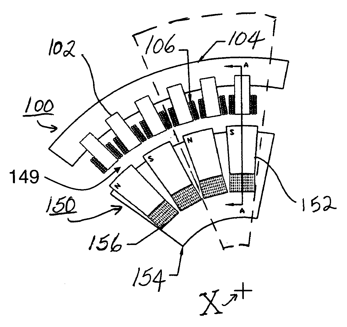
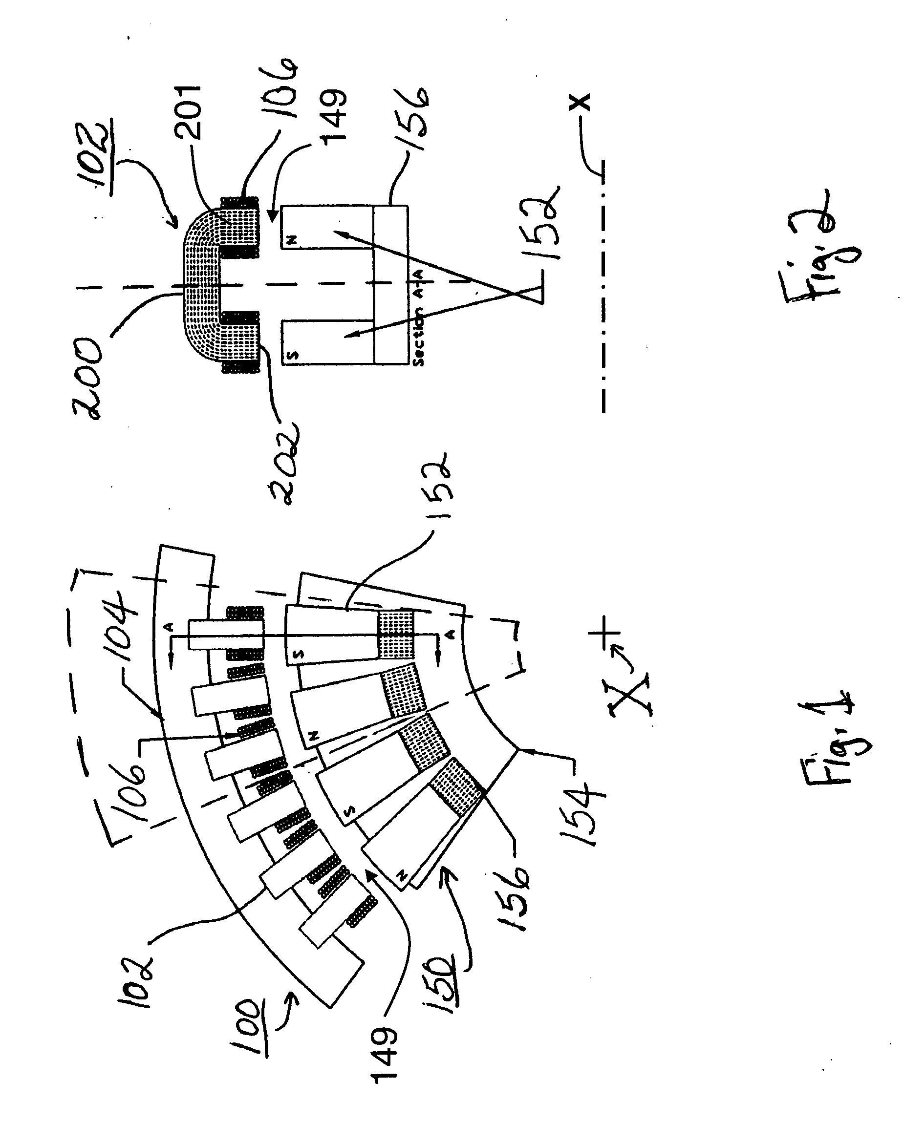
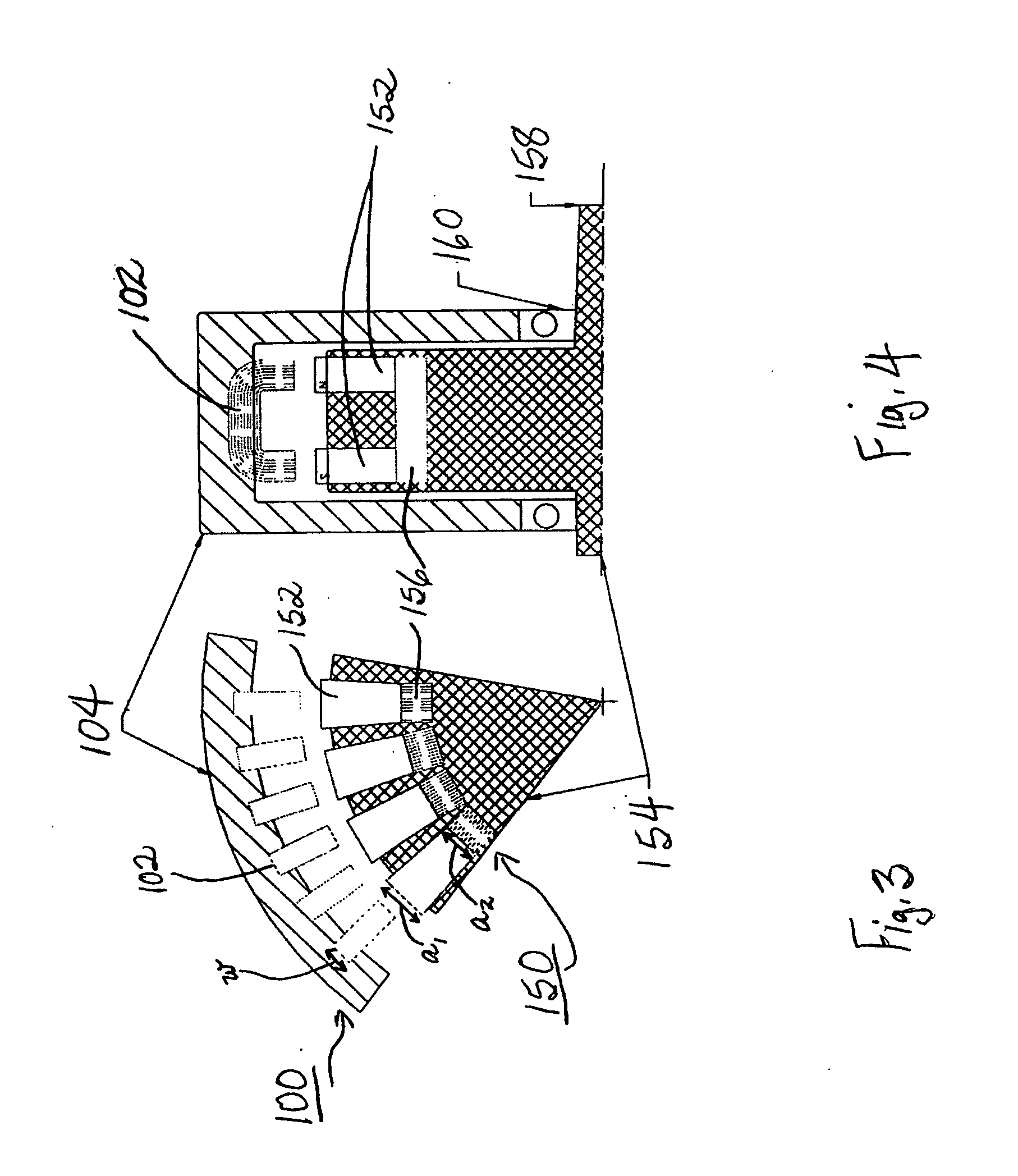
[0018]There is provided a radial airgap electric machine having a rotor and a stator assembly, the stator assembly including magnetic cores made from low-loss material capable of high frequency operation. Preferably, the stator's soft magnetic cores are made of at least one of amorphous, nanocrystalline, grain-oriented Fe-based material or non-grain-oriented Fe-based material and have a horseshoe-shaped design wound with stator windings on each end. The stator cores are coupled to one or more rotors. The inclusion of amorphous, nanocrystalline or flux-enhancing Fe-based magnetic material in the present electrical device enables th

Problems solved by technology

While it is generally believed that motors and generators having rotors constructed with advanced permanent magnet material and stators having cores made with advanced, low-loss soft materials, such as amorphous metal, have the potential to provide substantially higher efficiencies and power densities compared to conventional radial airgap motors and generators, there has been little success in building such machines of either axial or radial airgap type.
Previous attempts at incorporating amorphous material into conventional radial airgap machines have been largely unsuccessful commercially.
Amorphous metal has unique magnetic and mechanical properties that make it difficult or impossible to directly substitute for ordinary steels in conventionally designed motors.
These and other prior art designs have proved too costly and difficult for making a radial airgap motor u

Method used


Image

  • Radial airgap, transverse flux machine
  • Radial airgap, transverse flux machine
  • Radial airgap, transverse flux machine

Examples


example 1

DESIGN EXAMPLE 1

[0129]The beneficial use of low core loss stator magnetic materials in combination with a low SPP configuration is apparent from the following analysis, in which machines made with conventional motor steel (M19, a 26-gage, 3% silicon iron, non-oriented alloy) are compared with machines employing an advanced, low core loss, Fe-based amorphous magnetic material, METGLAS® 2605SA1. Machines employing these materials typically are designed to operate at peak working flux levels Bmax of 1.6 and 1.2 T, respectively. Although both materials have higher absolute saturation flux density, machine design invariably contemplates some allowance so that locally higher flux levels to not reach absolute saturation and to account for the loss of saturation flux density attendant to temperature increases.

[0130]The principal loss mechanisms in machines are ohmic (Joule) heating in the phase windings and core loss in the soft magnetic components. The values of these terms depend strongly...

example 2

DESIGN EXAMPLE 2

[0143]A more extensive consideration of the effect of soft magnetic material and SPP selection is carried out using the machine configurations delineated in Table II below. In particular, for each configuration six parameters are chosen to be either the minimum or maximum value listed, thus producing the 26=64 configurations of machines representing all the possible permutations of the listed design parameters.

TABLE IIDynamoelectric Machine Configuration ParametersParameterunitsminmaxRsradius of airgapmm50500tlength of core in axial directionmm50500qlength of core in radial directionmm10100Rrotational speedrpm100010000Stooth count (=slot count)6120κratio of tooth area to airgap area0.100.90(κ = w × t / z)

[0144]For each configuration and for a series of possible SPP values ranging from 0.5 to 4, the theoretical efficiency is calculated using the approximate analysis represented in equations (8a) and (8b) set forth above, using either AM or M19 as the stator core materia...

example 3

DESIGN EXAMPLE 3

[0145]The analysis of Example 2 is further refined to account for certain departures from ideal behavior that affect actual designs. In particular, the following effects are included:[0146]1) The extra space in each slot needed for wire insulation. This is in effect a penalty to high slot count designs, since this amount is fixed and not a percentage of slot space, and is measured in the thickness of the insulation system.[0147]2) The effect of parasitic high frequency losses in the windings. Frequency is function of the selected SPP, and a penalty to the winding resistance can be applied as a square of the frequency, The term used is

1+Coeff·(f1000)2(9)[0148]3) Include a term similar to that above, but applied to the core losses.[0149]4) Correction for the actual mass densities of M19 and AM (7.8 and 7.2 g / cm3, respectively).[0150]5) Correction for the imperfect focusing of flux from the rotor magnets across a wide airgap into many small teeth at SPP [0151]6) Recogni...


PUM


Abstract

A radial gap, transverse flux dynamoelectric machine comprises stator and rotor assemblies. The rotor assembly comprises at least two axially spaced, planar rotor layers having equal numbers of magnetic poles of alternating polarity disposed equiangularly about the rotor peripheral circumference. A magnetically permeable member optionally links adjacent rotor magnets. The stator assembly comprises a plurality of amorphous metal stator cores terminating in first and second polefaces. The cores are disposed equiangularly about the peripheral circumference of the stator assembly with their polefaces axially aligned. Respective first and second polefaces are in layers radially adjacent corresponding rotor layers. Stator windings encircle the stator cores. The device is operable at a high commutating frequency and may have a high pole count, providing high efficiency, torque, and power density, along with flexibility of design, ease of manufacture, and efficient use of magnetic materials.

Description

RELATED U.S. APPLICATION DATA[0001]This application is a continuation-in-part of co-pending U.S. application Ser. No. 10 / 846,041, filed Jun. 9, 2004, and entitled “Radial Airgap, Transverse Flux Motor,” and further claims the benefit of co-pending U.S. Provisional Application Ser. No. 60 / 478,074, filed Jun. 12, 2003, and entitled “Radial Airgap Transverse Flux Motor Using Amorphous, Nanocrystalline Grain-Oriented Fe-Based Materials Or Non-Grain-Oriented Fe-Based Materials,” both of which are incorporated herein in the entirety by reference thereto.BACKGROUND OF THE INVENTION[0002]1. Field of the Invention[0003]The present invention relates generally to a dynamoelectric rotating machine, and more particularly, to an electric motor, generator, or regenerative motor that is highly efficient and has improved performance characteristics as a result of the use therein of advanced magnetic materials.[0004]2. Description of the Prior Art[0005]The electric motor and generator industry is con...

Claims


Application Information

Patent Timeline
IPC IPC(8): H02K1/02H02K1/22
CPCH02K21/12H02K21/16H02K21/185H02K2201/12
Inventor HIRZEL, ANDREW D.
Owner HIRZEL ANDREW D
Why Eureka
Try Eureka