
Process For Producing a Coating Based on an Oxide Ceramic that Conforms to the Geometry of a Substrate Having Features in Relief

a technology of oxide ceramic and relief, applied in the direction of metallic material coating process, liquid/solution decomposition chemical coating, pretreatment surface, etc., can solve the problems of poor adhesion to the substrate, poor acuity of the edges of the relief, and low surface acuity, so as to achieve precise control of the thickness of the layer deposited. , the effect of increasing productivity

Inactive Publication Date: 2008-11-27
COMMISSARIAT A LENERGIE ATOMIQUE ET AUX ENERGIES ALTERNATIVES
View PDF7 Cites 10 Cited by
  • Summary
  • Abstract
  • Description
  • Claims
  • Application Information

AI Technical Summary

Benefits of technology

The invention is a process for producing coatings made of oxide ceramics that conform to the geometry of a substrate with features in relief. The process involves depositing a layer of a sol-gel solution on the substrate and heat-treating it to convert it into a ceramic. The sol-gel solution is prepared by mixing a solvent with a molecular precursor of the ceramic. The process has advantages such as being able to produce coatings on complex surfaces without heavy-duty equipment and being able to control the stoichiometry of the ceramic. The ceramics that can be used include oxides such as lead zirconium titanate, barium titanate, barium strontium titanate, lead zinc niobium titanate, lead magnesium niobate, lead titanate, potassium calcium niobate, bismuth potassium titanate, potassium tantalate, and solid solutions of PMN and PT. The process also involves preparing a stable sol-gel solution by mixing the metal or metalloid molecular precursor with a solvent and an aliphatic monoalcohol.

Problems solved by technology

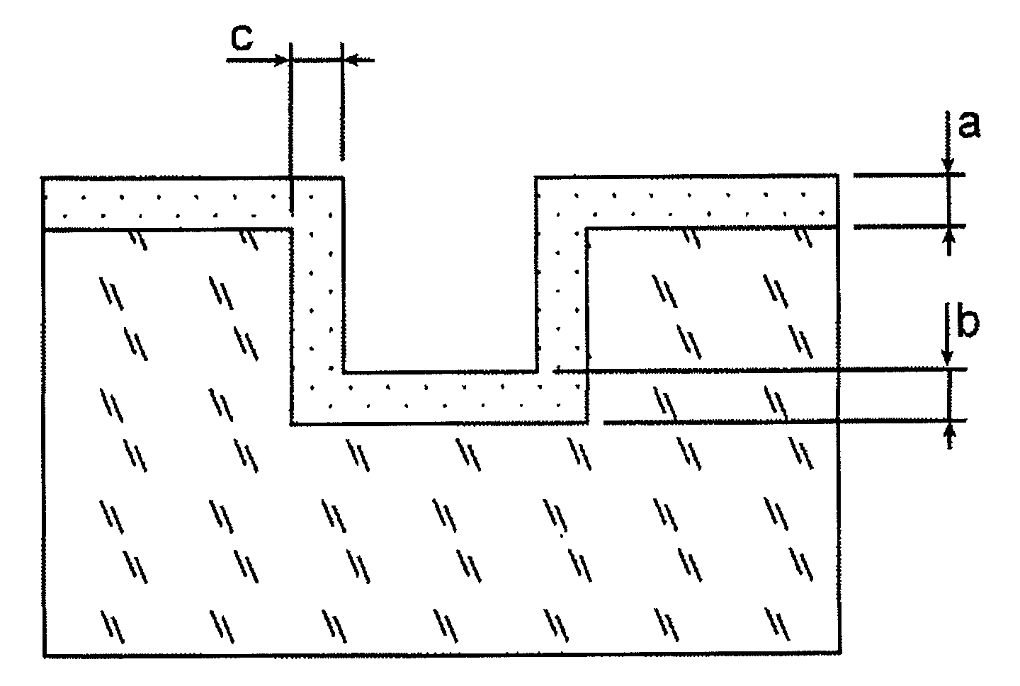
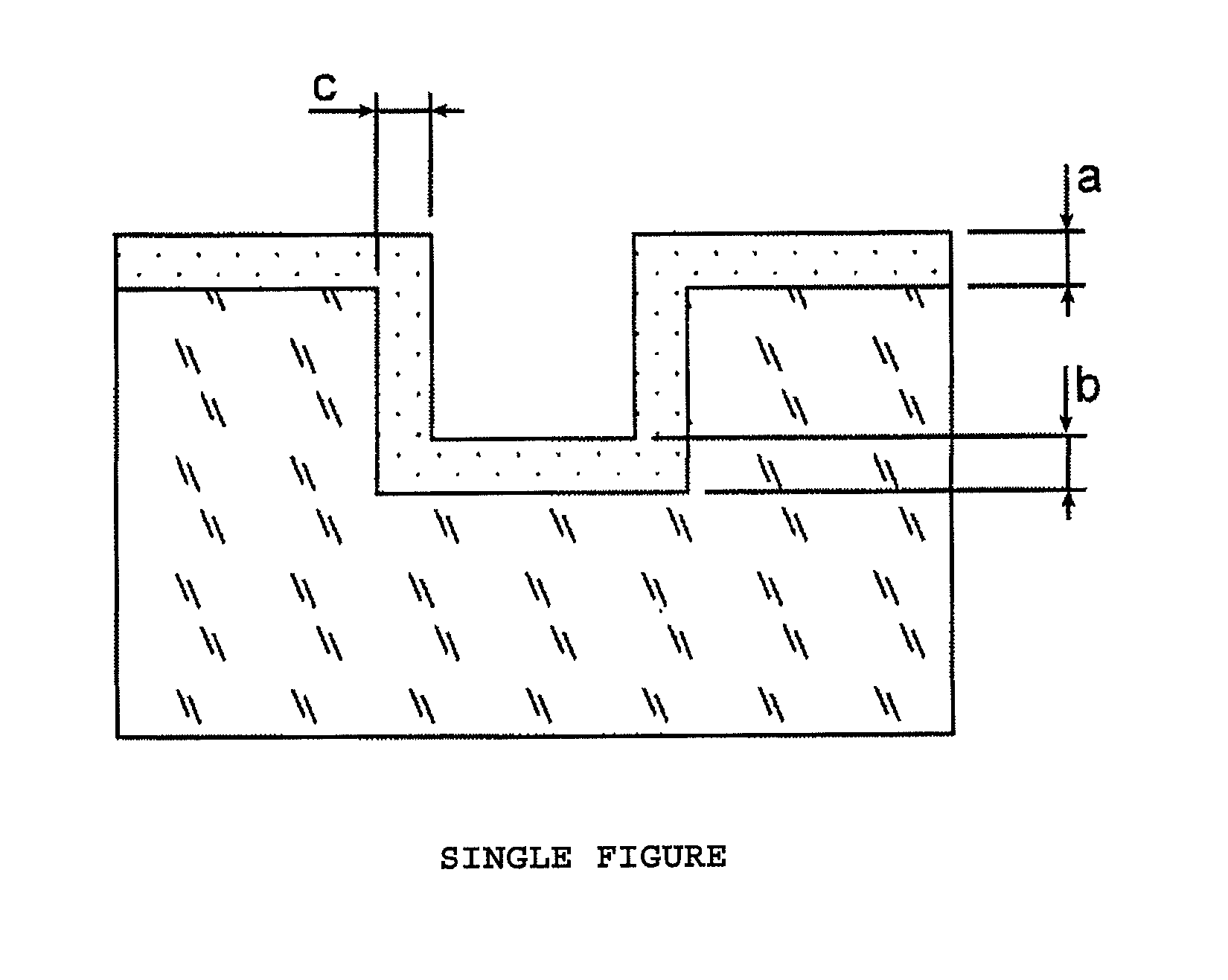
However, this method has the following drawbacks:the coatings obtained are not very dense;they are often contaminated by very reactive gases derived from the chemical reaction (hydrogen, halogens);they have a poor adhesion to the substrate; andthe coatings have poor acuity at the edges of the features in relief.
Although this method makes it possible to obtain denser layers, this method has proved to be difficult to implement, due to the equipment to be used, and costly, and does not ensure a uniform thickness of the layers on the substrates having features in relief.
In summary, whether it is by CVD or PVD, the coatings on the substrates having features of micron-scale size obtained by these techniques do not have a uniform thickness over the entire deposition length and have, in particular, overthicknesses at the edges of the features in relief.
This may cause, when the substrates thus coated are intended to be used as electronic components, variations in capacitance and also risks of breakdown at the edges of the features in relief.
However, in these documents it is a question of producing mouldings (that is to say the negative imprint) of the substrate and in no case of producing a coating of uniform thickness that matches the shape of the substrate.

Method used


Image

  • Process For Producing a Coating Based on an Oxide Ceramic that Conforms to the Geometry of a Substrate Having Features in Relief
  • Process For Producing a Coating Based on an Oxide Ceramic that Conforms to the Geometry of a Substrate Having Features in Relief

Examples


example 1

[0105]Described in this example is the experimental procedure for preparing a sol-gel solution that is a precursor of a lead zirconium titanate (PZT) ceramic, and also the process for depositing this solution, by dip coating, onto metallized silicon wafers, the surface of which has micron-scale features in relief, for the purpose of obtaining coatings that conform perfectly to the geometry of the substrate. The features used in this example are trenches having a depth of 1 μm, a width of 2 μm and spaced 2 μm apart.

a) Preparation of the Sol-Gel Solution Having a Nominal PbZr0.52Ti0.48O3 Composition

[0106]Firstly, a solution was prepared comprising a lead precursor. In order to do this, 751 g (1.98 mol) of lead acetate trihydrate and 330.2 g of ethylene glycol were weighed into a round-bottomed flask topped with a distillation assembly. The mixture was homogenized for 30 minutes at 70° C. so as to allow the lead acetate to completely dissolve. Then, the temperature of the homogenous so...

example 2

[0118]Described in this example is the experimental procedure for preparing a sol-gel solution that is a precursor of a lead zirconium titanate (PZT) ceramic, and also the process for depositing this solution, by spin coating, onto metallized silicon wafers, the surface of which has micron-scale features in 3 dimensions, for the purpose of obtaining coatings that conform perfectly to the geometry of the substrate. The features used in this example are trenches having a depth of 1 μm, a width of 2 μm and spaced 2 μm apart.

a) Preparation of the Sol-Gel Solution Having a Nominal PbZr0.52Ti0.48O3 Composition

[0119]Firstly, a solution was prepared comprising a lead precursor. In order to do this, 751 g (1.98 mol) of lead acetate trihydrate and 330.2 g of ethylene glycol were weighed into a round-bottomed flask topped with a distillation assembly. The mixture was homogenized for 30 minutes at 70° C. so as to allow the lead acetate to completely dissolve. Then, the temperature of the homoge...


PUM

PropertyMeasurementUnit
temperatureaaaaaaaaaa

Abstract

The invention relates to a process for producing layers made of oxide ceramic that conform to substrates having features in relief comprising:a step of depositing on said substrate a layer of a sol-gel solution that is a precursor of said ceramic;a heat treatment step of said layer with a view to converting it to the ceramic;said steps being optionally repeated one or more times, characterized in that the sol-gel solution that is a precursor of said ceramic is prepared by a process successively comprising the following steps:a) preparing a first solution by bringing the molecular precursor or precursors of the metals intended to be incorporated into the composition of the ceramic into contact with a medium comprising a diol solvent and optionally an aliphatic monoalcohol;b) leaving the solution obtained in a) to stand for a sufficient time needed to obtain a solution that has a substantially constant viscosity;c) diluting the solution obtained in b) to a predetermined amount with a dial solvent optionally identical to that from step a) or a solvent that is miscible with the dial solvent used in step a).

Description

TECHNICAL FIELD[0001]The subject of the present invention is a process for producing a coating based on an oxide ceramic that conforms to the geometry of a substrate having features in relief, in particular features of micron-scale size.[0002]The general technical field of the invention may therefore be defined as that of ceramic coatings for a substrate.[0003]The coatings have, for example, the role of modifying the properties of a substrate, such as the mechanical properties, the thermal properties, the electrical properties and the chemical properties and optical properties.[0004]The substrate coatings therefore find their application in numerous fields such as the fields of micro-electronics, optics or else energy.[0005]Thus, in the field of microelectronics, the tendency is to move towards systems of increasingly reduced size, involving the use of structures in relief to increase, in particular, the active surface of these structures. The production of such structures requires ...

Claims


Application Information

Patent Timeline
Patent Type & Authority Applications(United States)
IPC IPC(8): B05D3/10
CPCC23C18/1208C23C18/1225C23C18/1254
Inventor LEBRETTE, SEVERINEBOY, PHILIPPEBELLEVILLE, PHILIPPEMONTOUILLOUT, YVES
Owner COMMISSARIAT A LENERGIE ATOMIQUE ET AUX ENERGIES ALTERNATIVES
Learn More