Optical microprobe for blood clot detection

Inactive Publication Date: 2008-12-04
THE BOARD OF TRUSTEES OF THE UNIV OF ILLINOIS
View PDF14 Cites 30 Cited by
  • Summary
  • Abstract
  • Description
  • Claims
  • Application Information

AI Technical Summary

Benefits of technology

[0022]Any of the methods and systems provided herein are capable of use in a wide variety of surgical situations, including preoperative, intraoperative and/or postoperative. Preoperative refers to assessment prior to surgery, such as vessel evaluation for surgical intervention related to one or more of: brain aneurysms, ischemic strokes, arteriovenous malformation (AVM), peripheral artery disease, reconstructive plastic surgery, moyamoya disease. Intraoperative includes surgical situations including vascular manipulation and/or transitory vascular clamping where clot development is a concern. Examples where such manipulatons occur are with insertion/removal of vascular stents, bypass anastomoses for revascularization including coronary and carotid bypass surgery, bypass anastomoses for revascularization of peripheral vessels as in the treatment of deep vein thrombosis. Methods and devices presented herein provide for rapid real

Problems solved by technology

A major complication during vascular surgery is blood clot formation.
Blood clots adversely impact blood flow, result in tissue damage related to hypoxia, and are associated with other serious medical conditions such as stroke.
The drawback of those systems is that although they may identify a vessel obstruction (e.g., a blood clot), they are unable to localize the position or the extent of the obstruction.
This is often a time-consuming procedure, increasing total surgical time and placing the patient at additional risk.
Furthermore, the multiple cuts to the vessel that are often associated with surgically locating a blood clot are not conducive to vascular health.
When blood clots form during neurosurgery, blood flow is often reduced in the vessel containing the clot (depending on the cross-sectional area of the lumen blocked by the clot) and so the brain tissue volume irrigated by that vessel may become hypoxic.
If hypoxic conditions persist, temporary or even permanent brain damage may result.
Whi

Method used


Image

  • Optical microprobe for blood clot detection
  • Optical microprobe for blood clot detection
  • Optical microprobe for blood clot detection

Examples


Example

EXAMPLE 1

Optical System for Detecting Clots

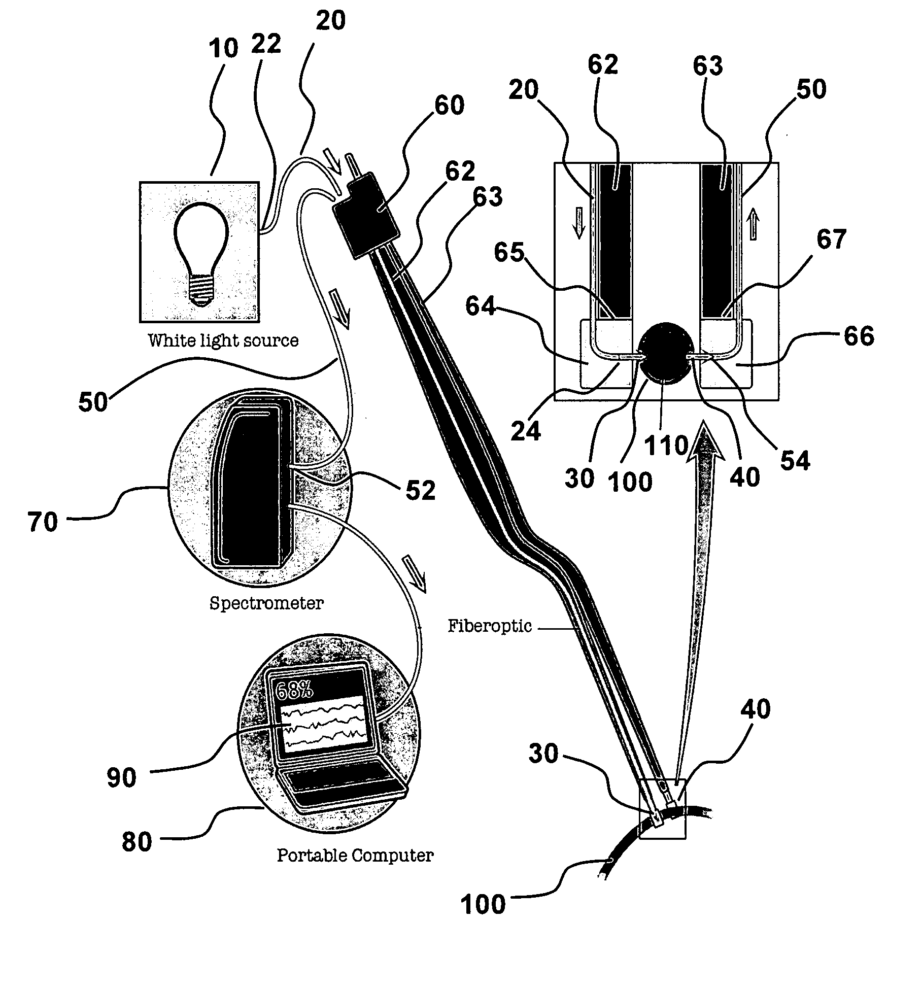
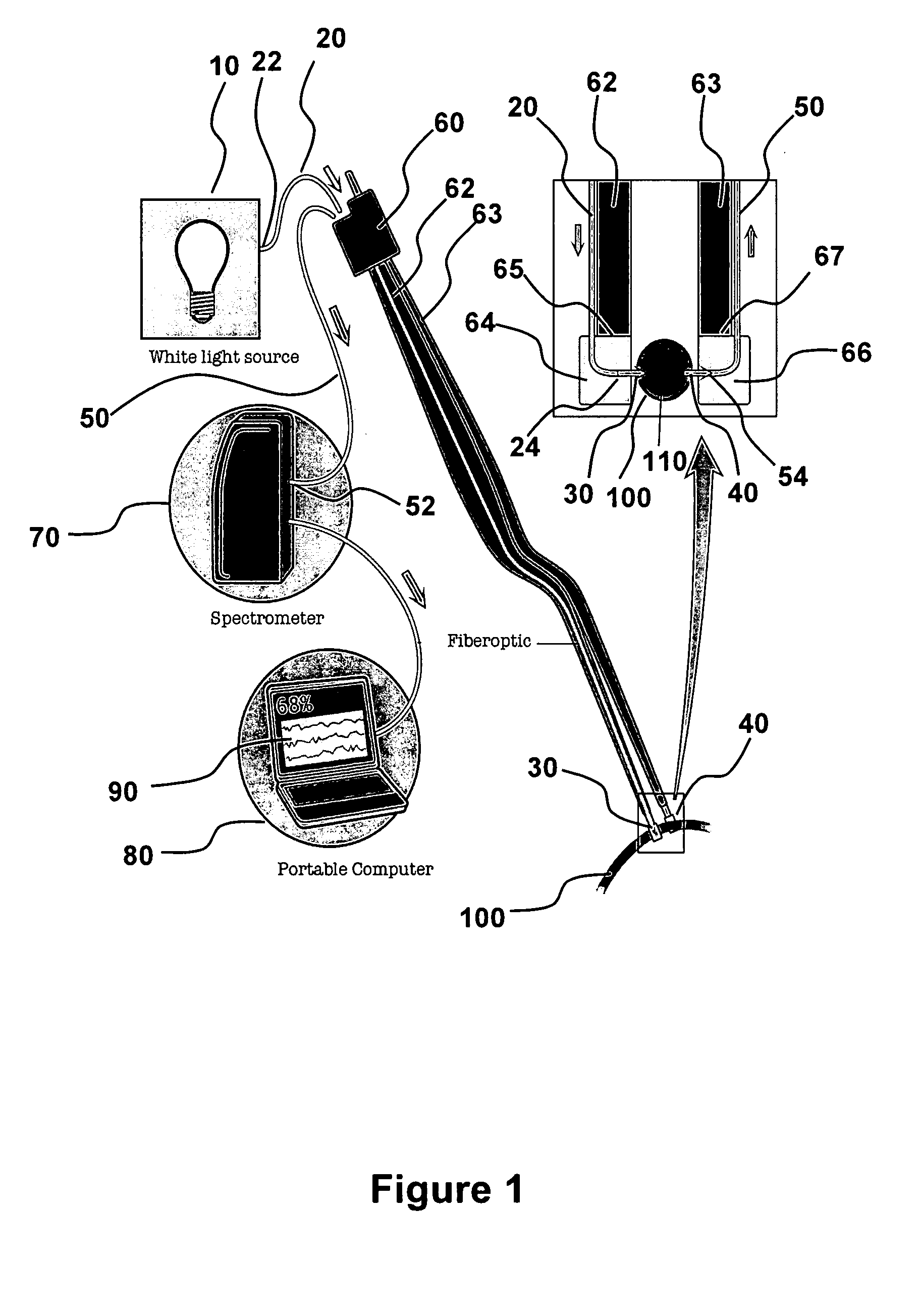
[0053]Referring to FIG. 1, electromagnetic radiation (“emr”) source 10 is connected to first fiber optic strand 20 at proximal end 22 and positioned to illuminate blood vessel 100 with emr 30 from distal end 24. A second fiber optic strand 50 collects emr 40 at distal end 54 that has traveled through blood vessel 100. The collector fiber optic 50 transmits the collected emr 40 to a detector 70 that is optically connected at second strand proximal end 52. The detector 70 is illustrated as a spectrometer that is able to measure an optical property of the collected emr 40. In an aspect, the optical property is the intensity of emr 40 (or a parameter obtained therefrom, such as absorbance, relative absorbance, or absorption coefficient) at one or more wavelengths. In an aspect, the optical property is assessed over a wavelength range, such as a spectrum of intensity or absorbance, including a wavelength range that spans all, or a portion of the...

Example

EXAMPLE 2

In Vitro Clot Detection

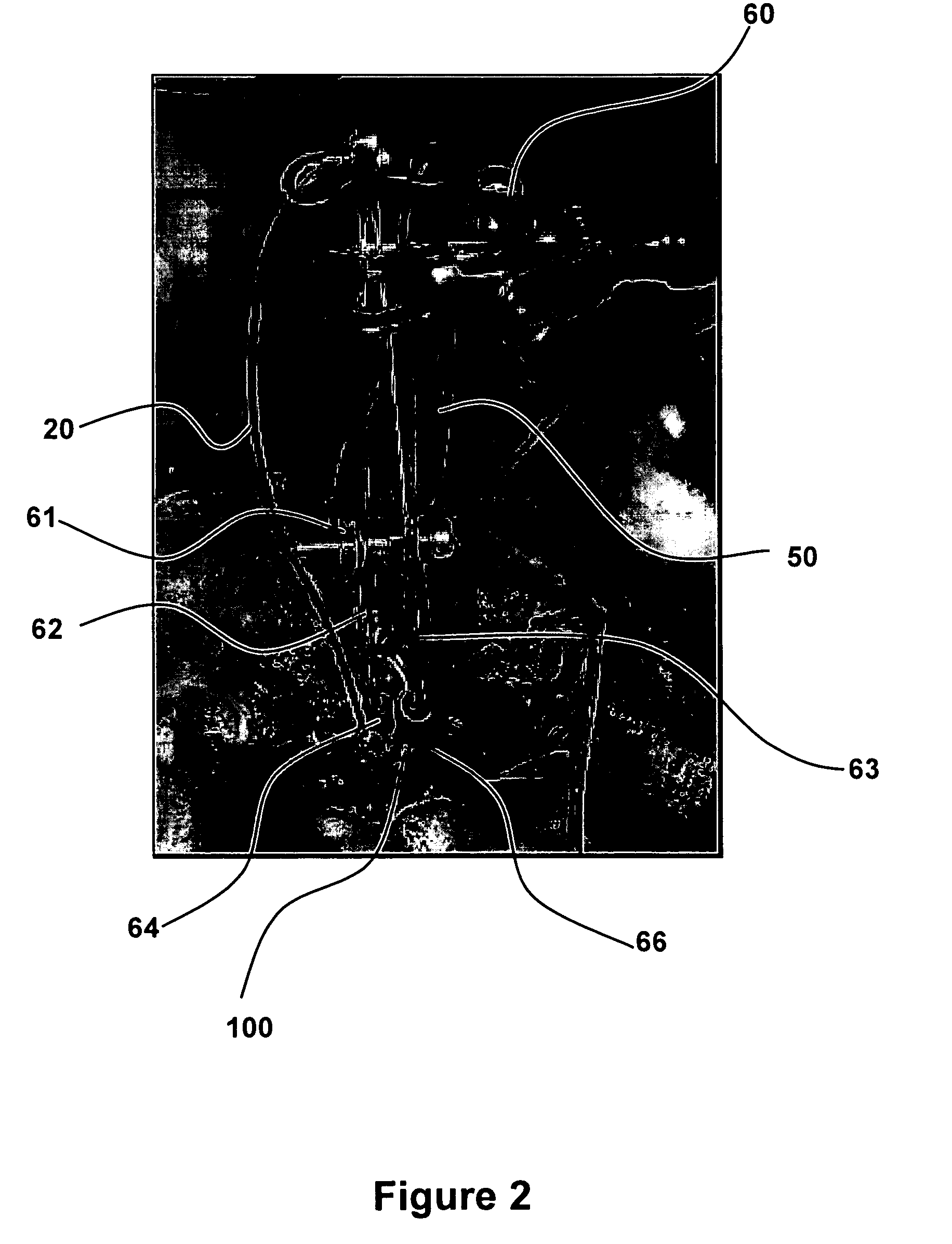
[0065]Whole blood from the animal is collected and deposited in a cuvette to generate a blood clot. The device pictured in FIGS. 1 and 2 is used to obtain spectral information during the clotting process. Once the blood is completely clotted inside the cuvette, spectral analysis with a spectrometer characterizes and stores the spectral components. Spectral components, with respect to the spectrum over the NIR, refers to the influence of RBCs, and specifically Hb that is either oxygen bound or oxygen unbound, and clot components. Without wishing to be constrained to any particular theory, because the main component of the blood clot is trapped red blood cells that are unable to re-oxygenate, the blood clot spectrum is believed to be similar to the spectrum of HHb.

[0066]FIG. 4 provides the absorption spectrum of clotted blood in a cuvette. The rapidly fluctuating spectrum is the raw intensity data of the blood. The smooth curve is the relative absorptio...

Example

EXAMPLE 3

Clot Detection in Blood Vessels

[0071]The optical microprobe system used for the in vitro experiments is used on ten six-month old male rats (Rattus Norvergicus Wistard) weighing about 500 g. During the procedure the animals are anesthetized with Ketamine (100 mg / kg), Xylazine (5 mg / kg) and Acepromazine (1.0 mg / kg). Depth of anesthesia is tested by foot pinch every 15 minutes. Supplemental doses of Ketamine 30 mg / kg and Xylasaline 1.75 mg / kg are given as necessary. In order to ensure adequate ventilation and oxygenation of the tissues, a traqueostomy is performed that connects the airway to a ventilator. The ventilator is set by visually observing the degree of lung expansion. The average breath per minute is about 85, producing an average tidal volume of 1.5 mL. The minute volume is 100 mL / min (range 75-130 mL / min). Because this technique is highly sensible to changes in hematocrit and the surgery can result in animal bleeding, measurements of capillary hematocrit and hemog...


PUM


Abstract

The invention is devices and related methods for detecting blood clots in a blood vessel. An optical microprobe is configured to illuminate a blood vessel with electromagnetic radiation corresponding to the near-infrared portion of the electromagnetic spectrum. The optical microprobe has a pair of fiber optic strands configured for transmission spectroscopy to obtain the absorption spectrum generated by the components within the blood vessel. Because blood clots generate a detectable and unique spectrum, the presence or absence of the blood clot is determined by examining the blood vessel absorption spectrum. A specially-designed holder is configured to stably position the optical microprobe relative to the blood vessel and is used to facilitate precise blood clot detection along a length of blood vessel.

Description

CROSS REFERENCE TO RELATED APPLICATIONS[0001]This application is a continuation-in-part of PCT / US2006 / 061742 filed Dec. 7, 2006 which claims benefit of U.S. Provisional Application No. 60 / 748,289 filed Dec. 7, 2005, each of which are incorporated herein by reference in their entirety to the extent not inconsistent herewith.BACKGROUND OF THE INVENTION[0002]A major complication during vascular surgery is blood clot formation. Blood clots adversely impact blood flow, result in tissue damage related to hypoxia, and are associated with other serious medical conditions such as stroke. The present invention relies on the finding that blood clots in a blood vessel generate a unique and specific spectrum detectable by transmission spectroscopy. The devices and methods of the present invention non-invasively illuminate the blood vessel and by transmission spectroscopy determine efficiently and reliably whether a blood clot is present within the blood vessel. The devices and methods disclosed ...

Claims


Application Information

Patent Timeline
IPC IPC(8): A61B5/02
CPCA61B5/0075A61B5/0086A61B5/02007A61B17/22A61B19/52A61B19/5225A61B2017/00778A61B2019/5206A61B2019/5217A61B90/36A61B90/37A61B2090/306A61B2090/3614
Inventor GATTO, RODOLFOD'AMICO, ENRICOMANTULIN, WILLIAM W.GRATTON, ENRICOCHARBEL, FADY
Owner THE BOARD OF TRUSTEES OF THE UNIV OF ILLINOIS
Why Eureka
Try Eureka