Light-emitting material, light emitting-element, light-emitting device, electronic device, and method for manufacturing thereof

Inactive Publication Date: 2009-01-08
SEMICON ENERGY LAB CO LTD
View PDF18 Cites 4 Cited by
  • Summary
  • Abstract
  • Description
  • Claims
  • Application Information

AI Technical Summary

Benefits of technology

[0021]A light-emitting material of the present invention which includes a compound including at least gallium and manganese can be a light-emitting material with high luminance.
[0022]The light-emitting material of the present invention has high electric conductivity and low resistance. Therefore, a light-emitting element using the light-emitting material of th

Problems solved by technology

Although the inorganic light-emitting element has more excellent material reliability than the organic light-emitting element, sufficient emission luminance and the like have not been obtained and various researches have b

Method used


Image

  • Light-emitting material, light emitting-element, light-emitting device, electronic device, and method for manufacturing thereof
  • Light-emitting material, light emitting-element, light-emitting device, electronic device, and method for manufacturing thereof
  • Light-emitting material, light emitting-element, light-emitting device, electronic device, and method for manufacturing thereof

Examples


embodiment mode 1

[0038]This embodiment mode will describe a light-emitting material for manufacturing a light-emitting element with high luminance. Note that the light-emitting material of this embodiment mode is a material that includes a base material, an element to be a luminescent center, and a compound including at least gallium and manganese.

[0039]As a base material used for the light-emitting material, sulfide, oxide, or nitride can be used. As sulfide, zinc sulfide, cadmium sulfide, calcium sulfide, yttrium sulfide, gallium sulfide, strontium sulfide, barium sulfide, or the like can be used, for example. As oxide, for example, zinc oxide, yttrium oxide, or the like can be used. As nitride, for example, aluminum nitride, gallium nitride, indium nitride, or the like can be used. Further, zinc selenide, zinc telluride, or the like, or ternary mixed crystals such as calcium gallium sulfide, strontium gallium sulfide, or barium gallium sulfide may be used.

[0040]As a luminescent center material in...

embodiment mode 2

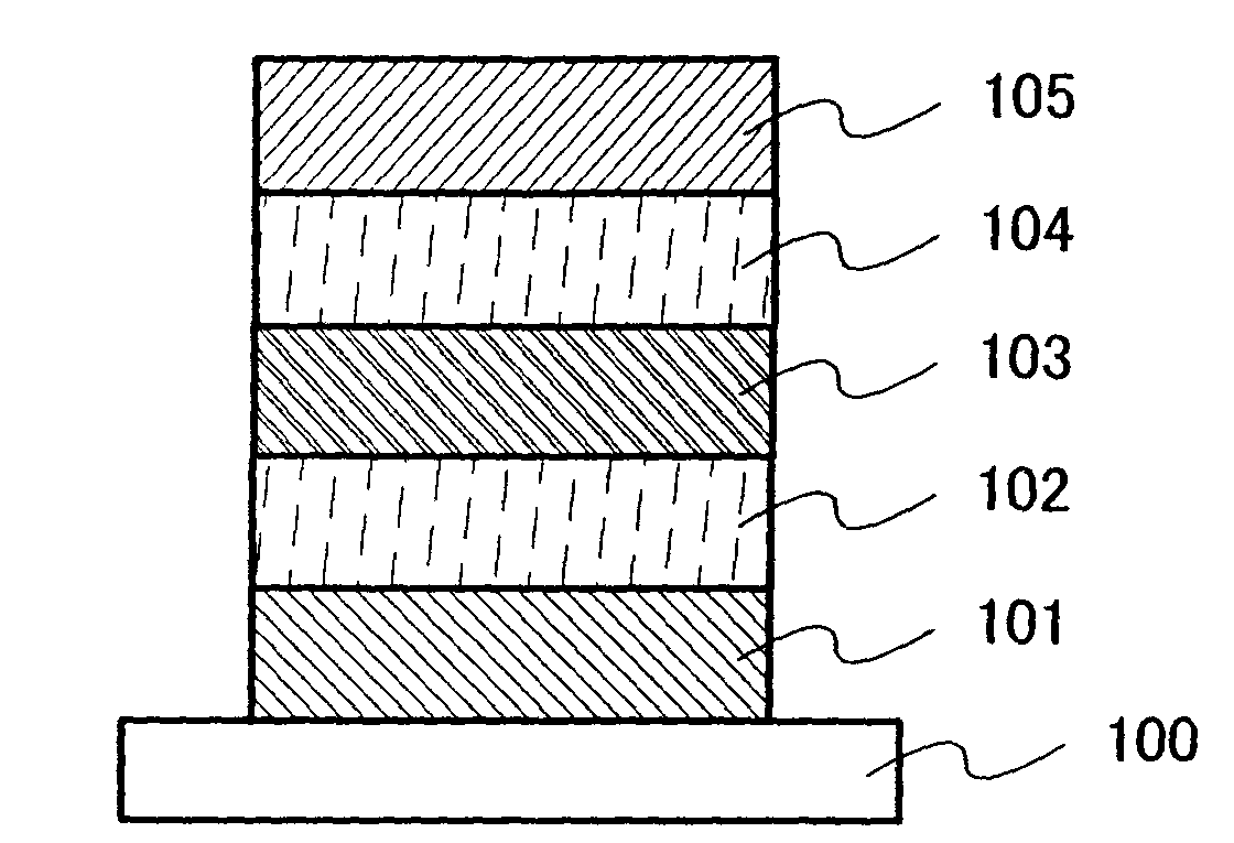
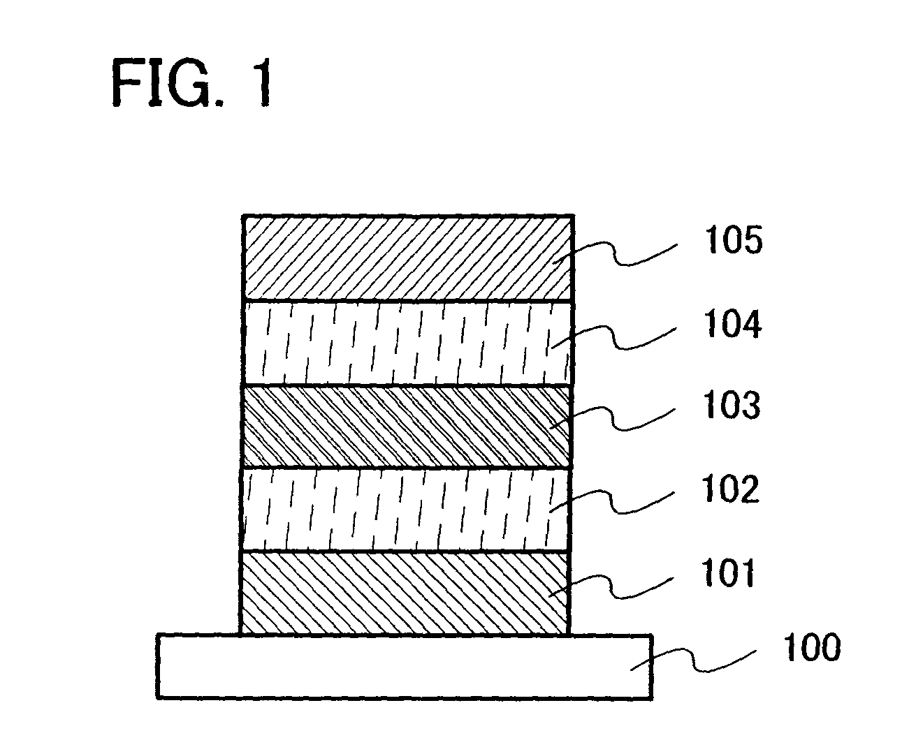
[0054]This embodiment mode will describe a light-emitting element formed using the material described in Embodiment Mode 1, with reference to FIG. 1. Note that in this embodiment mode, a thin-film light-emitting element is described.

[0055]A light-emitting element described in this embodiment mode has a structure where, as shown in FIG. 1, a first electrode 101 and a second electrode 105 are provided over a substrate 100, a light-emitting layer 103 is provided between the first electrode 101 and the second electrode 105, a first dielectric layer 102 is provided between the first electrode 101 and the light-emitting layer 103, and a second dielectric layer 104 is provided between the light-emitting layer 103 and the second electrode 105. Note that the structure of the light-emitting element is not limited to the one shown in FIG. 1, and a structure having only one of the first dielectric layer 102 and the second dielectric layer 104 may be employed. In this embodiment mode, descriptio...

embodiment mode 3

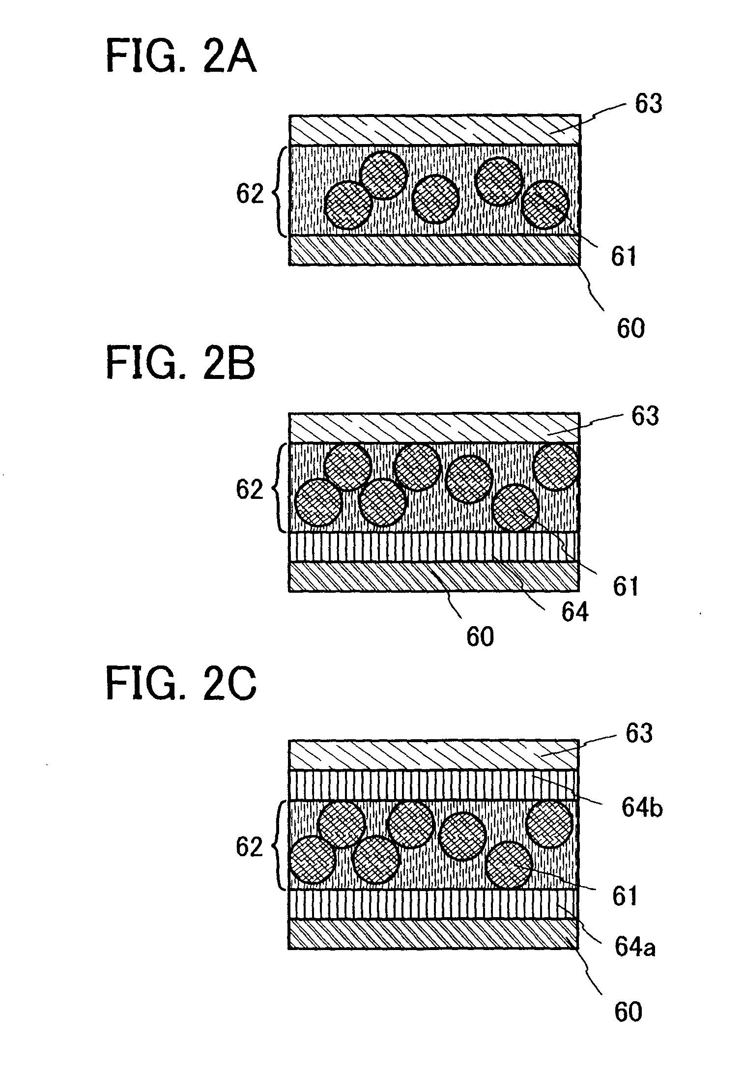
[0066]This embodiment mode will describe a structure of a dispersion-type light-emitting element formed using the material described in Embodiment Mode 1.

[0067]In the case of a dispersion-type light-emitting element, a film-form light-emitting layer is formed by dispersing particles of a light-emitting material into a binder. When particles with a desired size cannot be obtained depending on a method for forming a light-emitting material, the material may be processed into particulate forms by being ground in a mortar or the like. A binder is a substance for fixing particles of the light-emitting material in a dispersed state and holding the light-emitting material in a shape as a light-emitting layer. The particles of the light-emitting material are uniformly dispersed and fixed in the light-emitting layer with the binder.

[0068]In the case of a dispersion-type light-emitting element, a light-emitting layer can be formed by a droplet discharge method by which a light-emitting layer ...


PUM


Abstract

It is an object to provide a light-emitting material with higher emission luminance than conventional one in terms of a crystalline structure of the light-emitting material, as a light-emitting material using an inorganic compound. First baking is performed after mixing gallium arsenide, gallium phosphide, or gallium antimonide with manganese to form a first baked product, second baking is performed after mixing a base material with an element for forming a luminescent center material or a compound including the element to form a second baked product, and third baking is performed after mixing the first baked product with the second baked product, so that a light-emitting material is manufactured.

Description

BACKGROUND OF THE INVENTION[0001]1. Field of the Invention[0002]The present invention relates to a light-emitting material and a method for manufacturing the light-emitting material. The present invention further relates to a light-emitting element using electroluminescence. Moreover, the present invention relates to a light-emitting device and an electronic device each having the light-emitting element.[0003]2. Description of the Related Art[0004]In recent years, a display device in a television set, a mobile phone, a digital camera, or the like has been required to be flat and thin, and as a display device for meeting this requirement, a display device utilizing a self-luminous light-emitting element has attracted attention. One of the self-luminous light-emitting elements is a light-emitting element utilizing electroluminescence (EL), and this light-emitting element includes a light-emitting material interposed between a pair of electrodes and can provide emission from the light-...

Claims


Application Information

Patent Timeline
IPC IPC(8): H01J1/63C09K11/54C09K11/57C09K11/77
CPCC09K11/626H05B33/145C09K11/722
Inventor HOSOBA, MIYUKI
Owner SEMICON ENERGY LAB CO LTD
Why Eureka
Try Eureka