

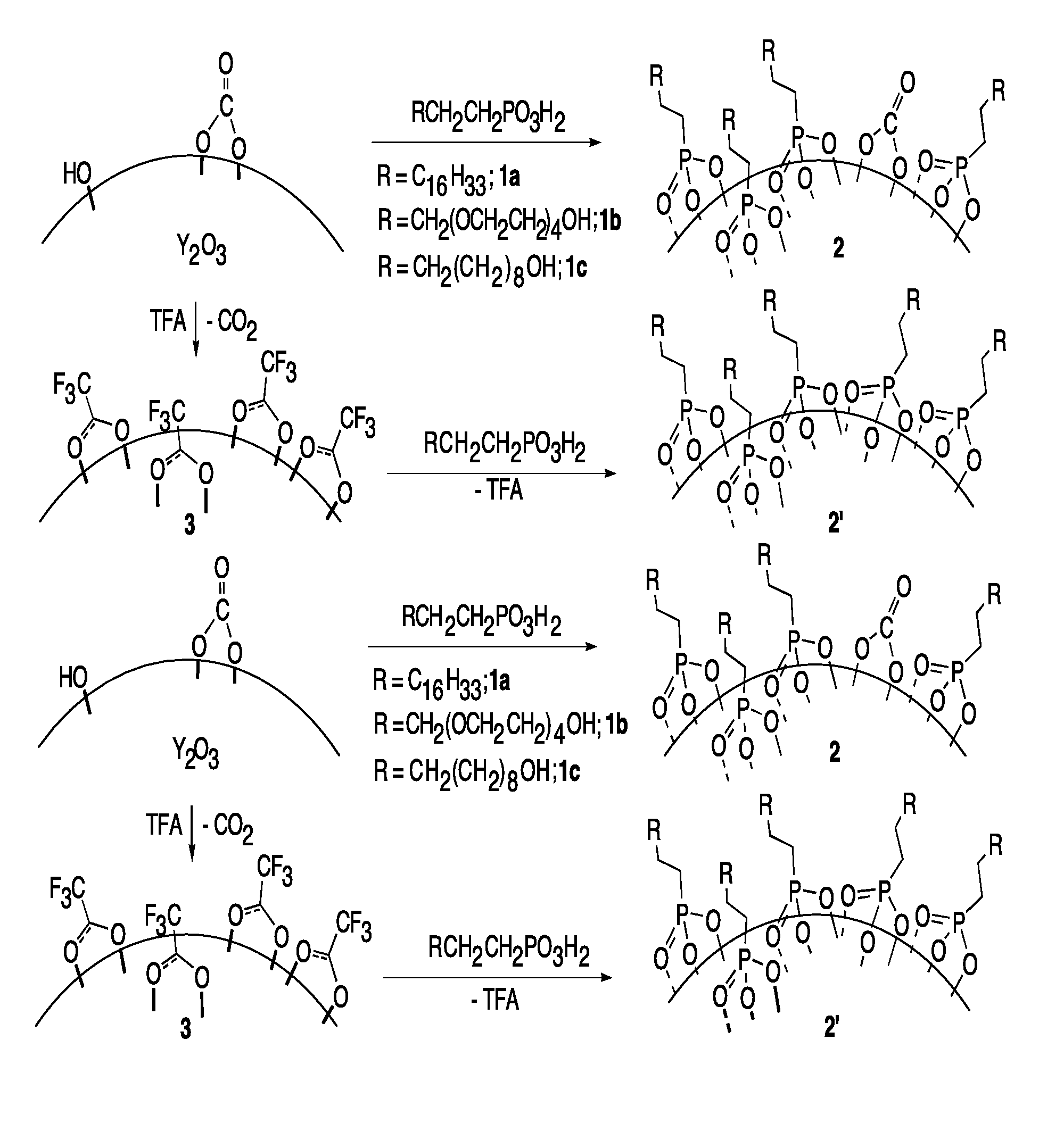
Nano-particle surface modification
a technology of nanoparticles and surface modifications, applied in the direction of powder delivery, granular delivery, packaged goods, etc., can solve the problems of limiting in vitro and compromising in vivo applications of nanoparticles, increasing particle size, and untreated nanoparticles are not without problems, so as to achieve effective cancer treatment
- Summary
- Abstract
- Description
- Claims
- Application Information
AI Technical Summary
Benefits of technology
Problems solved by technology
Method used
Image

Examples
example 1
Preparation of Acetoxy(tetra[ethyleneoxy])propyl Dimethyl Phosphonate
[0078]Dimethyl phosphite (2.481 g, 0.0226 mol) and acetoxy(tetra[ethyleneoxy]) monoallyl ether (2.095 g, 0.0076 mol) were added to a 50 mL three-necked flask fitted with a reflux condenser, an argon inlet, and a septum. The stirred solution was heated to 105° C. Tert-Butyl peroxybenzoate (0.1 mL, 5.26×10⁻⁴ mol) was added via syringe to initiate the radical addition. An additional portion of radical initiator was added after 1 h and again after 2 h of reaction time. After 4.5 h of total reaction time, the mixture was allowed to cool. The resulting oil was purified by silica column chromatography using increasing amounts (0-6%) of methanol in ethyl acetate to obtain a colorless oil (0.750 g, 25% yield).
[0079]1H NMR (300 MHz, CDCl3, δ): 4.21 (dd, J) 3.9, 5.4 Hz, 2H), 3.74 (d, J) 10.7 Hz, 6H), 3.72-3.56 (m, 14H), 3.51 (t, J) 6 Hz, 2H), 2.06 (s, 3H), 1.92-1.76 (m, 4H). 13CNMR (100 MHz, CDCl3, δ): 171.16, 70.86, 70.72, 7...
examples 2-3
Preparation of Octadecyldimethylphosphphonate and Undecyldimethylphosphonate
[0080]Example 1 was repeated using stoichiometric amounts of 1-octadecene and 1-undecene for acetoxy(tetra[ethyleneoxy])monoallyl ether. The title compounds were obtained.
example 4
Preparation of Hydroxyl(tetra[ethyleneoxy])propylphosphonic Acid (FIG. 4)
[0081]A solution of the dimethyl phosphate of Example 1 (0.271 g, 7.01×10⁻⁴ mol) in 15 mL of CH2Cl2 was added to a 50 mL three-necked flask equipped with a stir bar, an argon inlet, and a septum. The solution was stirred at room temperature under argon, and trimethylsilyl bromide (0.5 mL, 3.7901×10⁻³ mol) was added dropwise via syringe. The reaction mixture was stirred for 24 h. Methanol (0.109 g, 3.4001×10⁻³ mol) was then added, and the solution was stirred for an additional 24 h. Hydrochloric acid (1 mL, 5% HCl solution in deionized water) was added, and the mixture was stirred for 30 min before the layers were allowed to settle. The aqueous layer was collected, and the water was evaporated under reduced pressure to yield an orange oil (0.232 g, 104%). The product was >95% pure by 31P NMR spectroscopy, and no significant impurities were visible in the 1H or 13C NMR spectra so the hydroxyl(tetra[ethyleneoxy])p...
PUM
| Property | Measurement | Unit |
|---|---|---|
| Particle size | aaaaa | aaaaa |
| Particle size | aaaaa | aaaaa |
| Polarity | aaaaa | aaaaa |
Abstract
Description
Claims
Application Information