Aberration corrector and charged particle beam apparatus using the same

Active Publication Date: 2009-02-12
HITACHI HIGH-TECH CORP
View PDF4 Cites 39 Cited by
  • Summary
  • Abstract
  • Description
  • Claims
  • Application Information

AI Technical Summary

Benefits of technology

[0013]According to the present invention, since a multistage multipole is assembled using the multipole element as a building block, both the number of parts necessary for the assembly and the number of assembly steps are reduced compared to the conventional technology whereby the multistage multipole is assembled using the electrode as a building block. Moreover, since the multipole is assembled not by making the whole multipoles into a single piece but by using the building block of the multipole element, arrangement of the multipole element in an in-plane direct

Problems solved by technology

Although the each patent document described above discloses a technology of machining one stage of multipole with high precision, it discloses no technology of assembling manufactured multipoles in a stage direction with high precision.
However, when applying the electrical discharge machining method to collective formation of the multistage of multipoles, adjusting the inclination of the wire to become straight to an optical axis becomes difficult as the number of stages becomes large (that is, the multistage becomes long in the optical axis direction).
Therefore, it is difficult to maintain machining accuracy of unevenness of the multipole to a necessary level (typically, about ±5 μm in parallel to the optical axis).
If the machining accuracy of about ±5 μm is not maintainable, unnecessary parasitic aberration will occur

Method used


Image

  • Aberration corrector and charged particle beam apparatus using the same
  • Aberration corrector and charged particle beam apparatus using the same
  • Aberration corrector and charged particle beam apparatus using the same

Examples


Example

First Embodiment

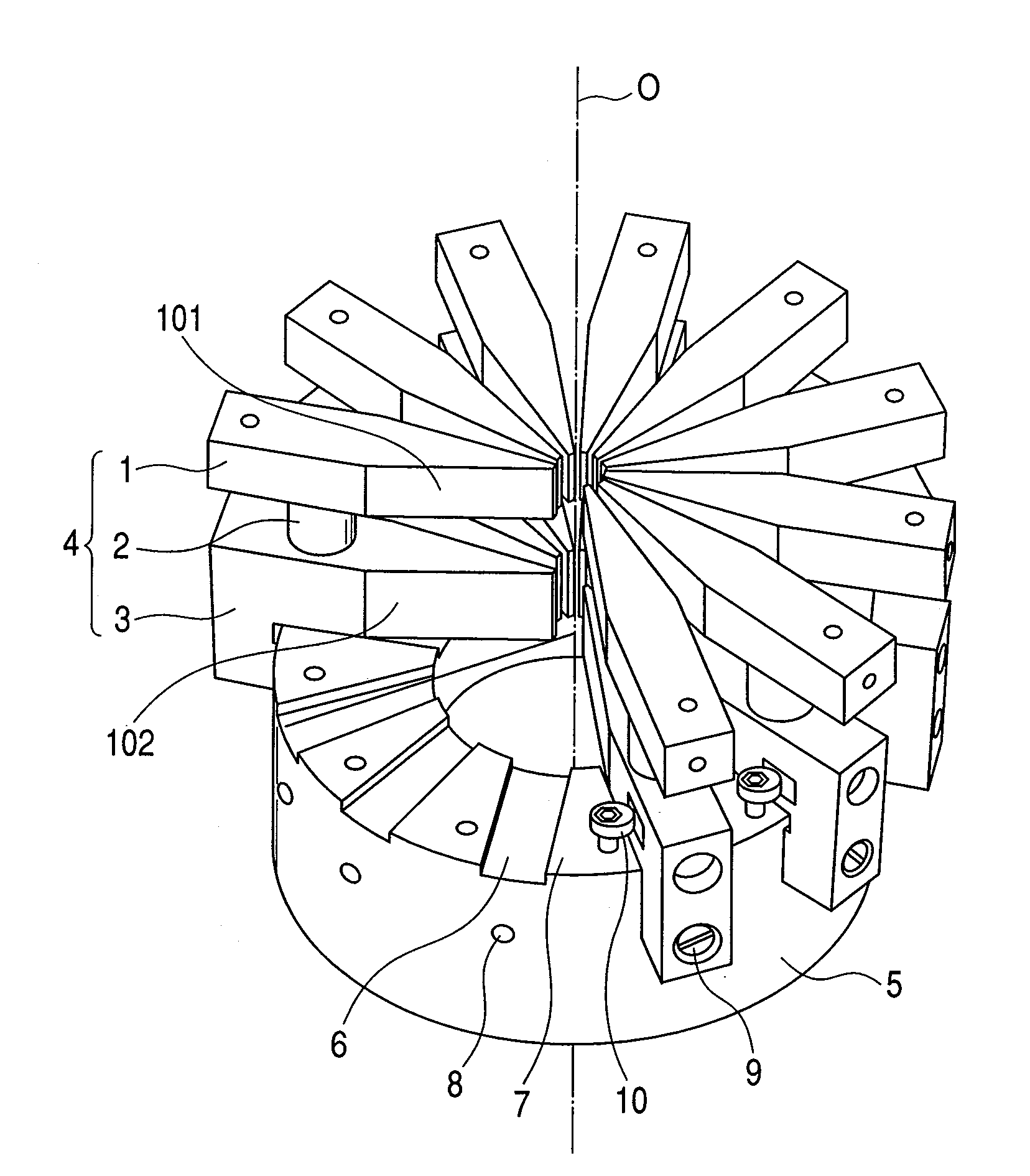
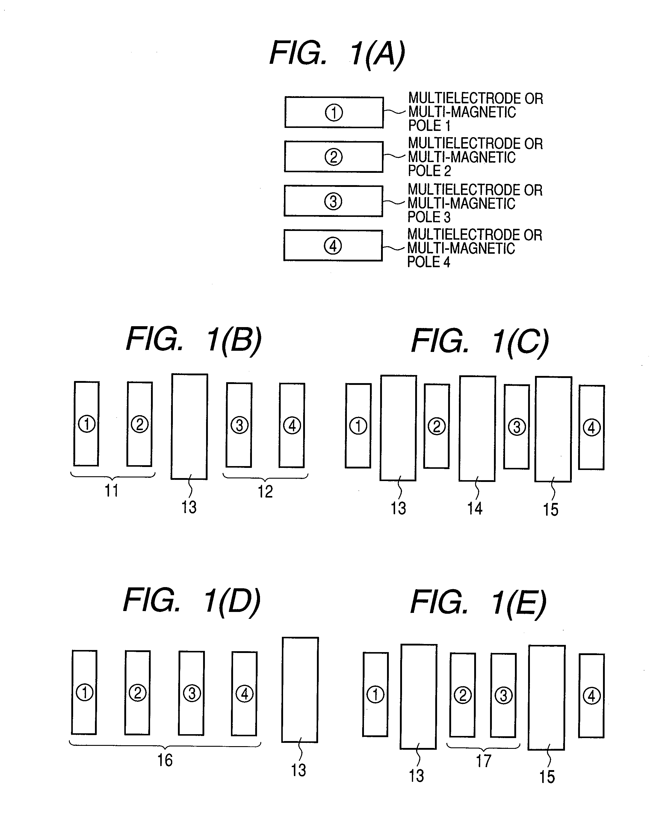
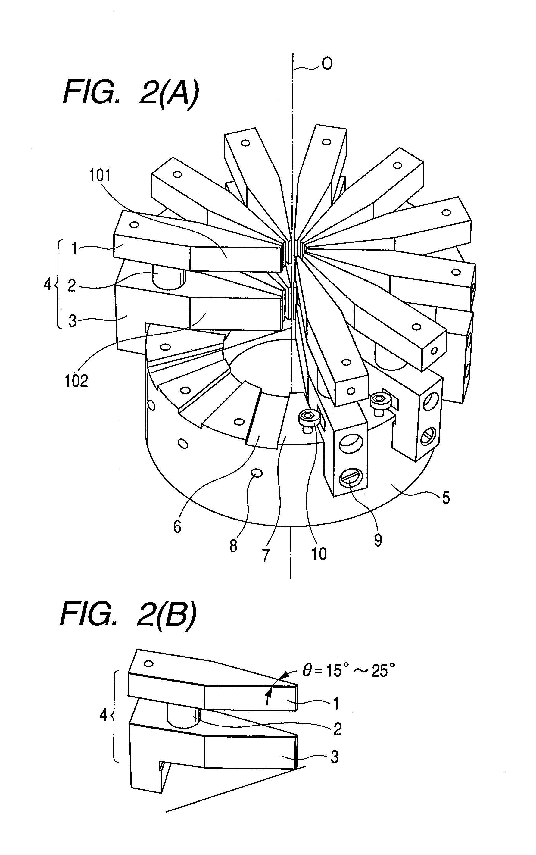
[0026]In this embodiment, an embodiment will be explained in which the multipole element made by bonding the electrode and the magnetic pole in upper and lower two stages, a two-stage multipole is constructed using the electromagnetic multipole element, and the aberration corrector is constructed using the two-stage multipole elements. FIG. 2(A) shows an example of a two-stage dodecapole that is constructed using 12 multipole elements shown in FIG. 2(B). The multipole element shown in FIG. 2(B) is equivalent to a multipole element in which the two electrodes 11 of FIG. 1(B) has been fixed to the fixed base 13.

[0027]An electrode 1 obtained by cutting a non-magnetic metal (titanium etc.) whose thermal expansion rate is comparatively small into a predetermined shape is brazed to an electrode or magnetic pole 3 obtained by cutting a soft magnetic metal (Permalloy etc.) into a predetermined shape via an alumina prop 2 using silver braze, and so the above members 1, 2, and...

Example

Second Embodiment

[0040]This embodiment will explain an embodiment where the aberration corrector shown by the first embodiment is applied to a field emission SEM (FE-SEM), as an application example to a charged particle beam apparatus.

[0041]FIG. 4 shows a configuration example of the FE-SEM equipped with the aberration corrector that uses a brazed multistage multipole. This SEM is constructed with an SEM column 301 for irradiating or scanning an electron beam on a specimen, a specimen chamber 302 for housing the specimen stage, a controller 303 for controlling constituent parts of the SEM column 301 and the specimen chamber 302, etc. In FIG. 4, illustrations and explanations of an ion pump, a turbo molecular pump, vacuum piping, and a vacuum system control mechanism are omitted. The controller 303 is further connected with a data storage 376 for storing predetermined pieces of information, a monitor 377 for displaying an acquired image, an operation console 378 serving as a man-mach...

Example

Third Embodiment

[0049]FIG. 5 shows a configuration example of a critical dimension SEM (CD-SEM) equipped with the aberration corrector that uses a brazed multistage multipole. Since the configuration shown in FIG. 5 has many common parts to those of the configuration in FIG. 4, only parts that have different structures will be explained. In this embodiment, a Schottky emission gun 40 is used. A Schottky emitter 41 is an electron source that is made of tungsten single crystal into which oxygen, zirconium, etc. are diffused and uses the Schottky effect. In its vicinity, a suppressor electrode 42 and an extraction electrode 34 are provided. Schottky electrons are made to emit by heating the Schottky electron source 41 and impressing a voltage of about +2 kV at the extraction electrode 34. A negative voltage is impressed at the suppressor electrode 42 to suppress electron emission from any location of the Schottky electron source 41 other than its tip. Although an energy width and a lig...


PUM


Abstract

The present invention provides an aberration corrector giving excellent assembly accuracy but having fewer parts and fewer adjustment locations in number. In order to achieve it, a multistage multipole is formed by arranging plural combinations of electrodes around an optical axis using alignment blocks, each combination of electrodes being made by brazing-integrating plural electrodes with a ceramic material interposed therebetween.

Description

CLAIM OF PRIORITY[0001]The present invention claims priority from Japanese patent application JP 2007-206655, filed on Aug. 8, 2007, the content of which is hereby incorporated by reference into this application.BACKGROUND OF THE INVENTION[0002]The present invention relates to a structure of an aberration corrector used for a charged particle beam apparatus, and a charged particle beam apparatus equipped with the aberration corrector.[0003]In the charged particle beam apparatuses, such as the scanning electron microscope, the scanning transmission electron microscope, the transmission electron microscope, and the focused ion beam machining system, multipole (dipole, quadrupole, octapole, etc.) have been used for the deflector and the astigmatism corrector. In recent years, in order to correct spherical aberration and chromatic aberration of an objective lens with axially rotational symmetry, the aberration corrector made by combining the quadrupole, hexapole, octapole, etc. has been...

Claims


Application Information

Patent Timeline
IPC IPC(8): H01J3/14G01N23/04
CPCG01N23/20H01J37/153H01J2237/28H01J2237/032H01J2237/1534H01J37/26
Inventor KAWASAKI, TAKESHIMORIYA, NOBORUNAKANO, TOMONORIHIROSE, KOTOKO
Owner HITACHI HIGH-TECH CORP
Why Eureka
Try Eureka