

Organic electroluminescence device and material for organic electroluminescence device
a technology of electroluminescence device and organic electroluminescence, which is applied in the direction of discharge tube/lamp details, luminescence screen of discharge tube, organic chemistry, etc., can solve the problems of insufficient practical application of improved luminous efficiency and lifetime, short life of organic electroluminescence device, and considerable degradation of molecules, etc., to achieve long lifetime, high efficiency, and high efficiency
- Summary
- Abstract
- Description
- Claims
- Application Information
AI Technical Summary
Benefits of technology
Problems solved by technology
Method used
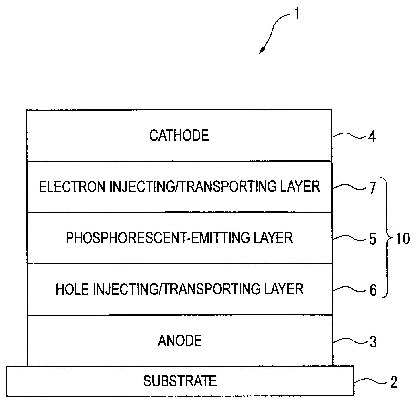
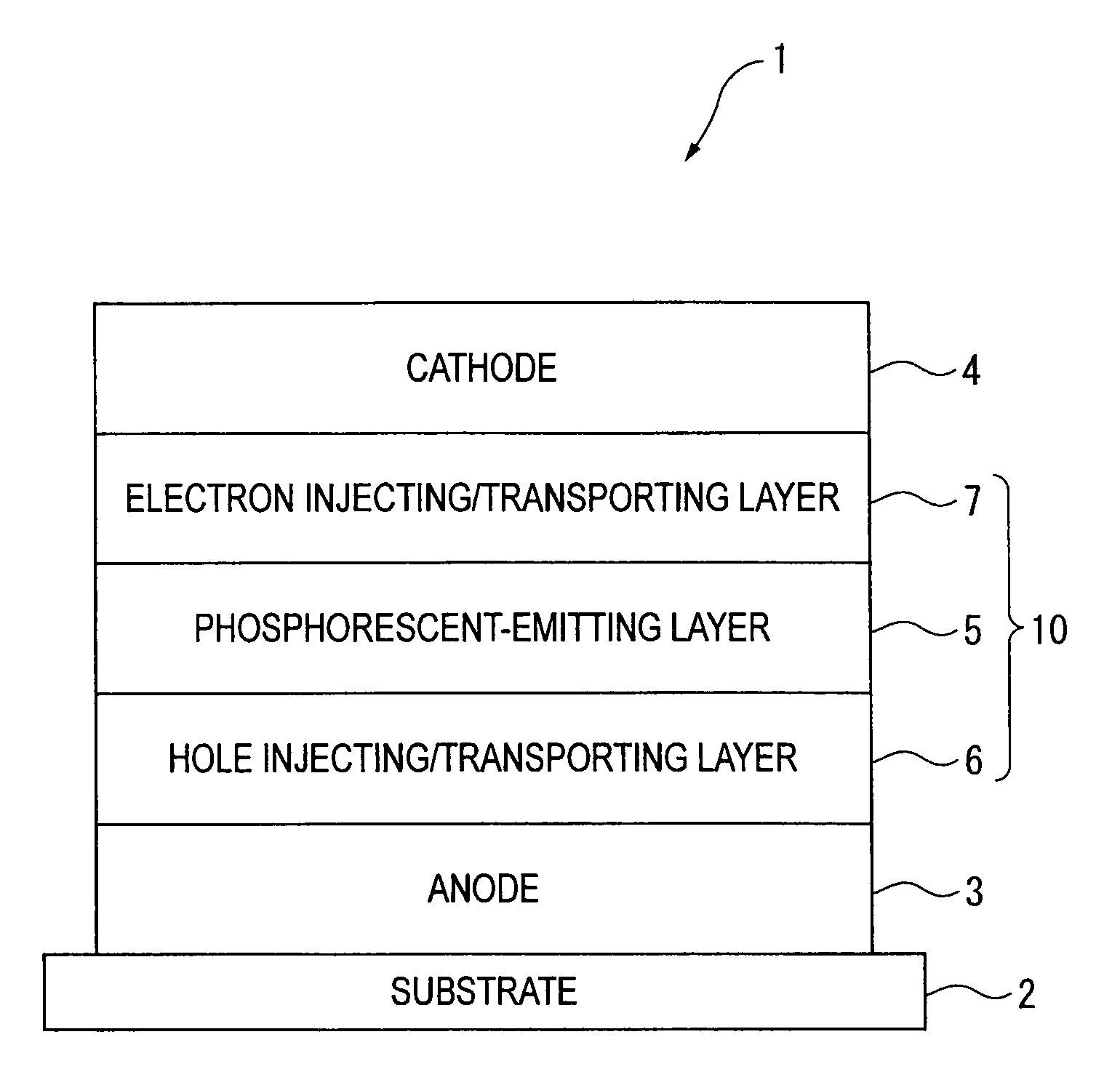
Image

Examples
synthesis example
[0248]Compounds according to the present invention can be synthesized by Suzuki-Miyaura cross coupling reaction.
[0249]Next, a manufacturing method of the host material according to the present invention will be described with reference to synthesis example(s). However, the present invention is not limited to the description made herein.
synthesis example 1
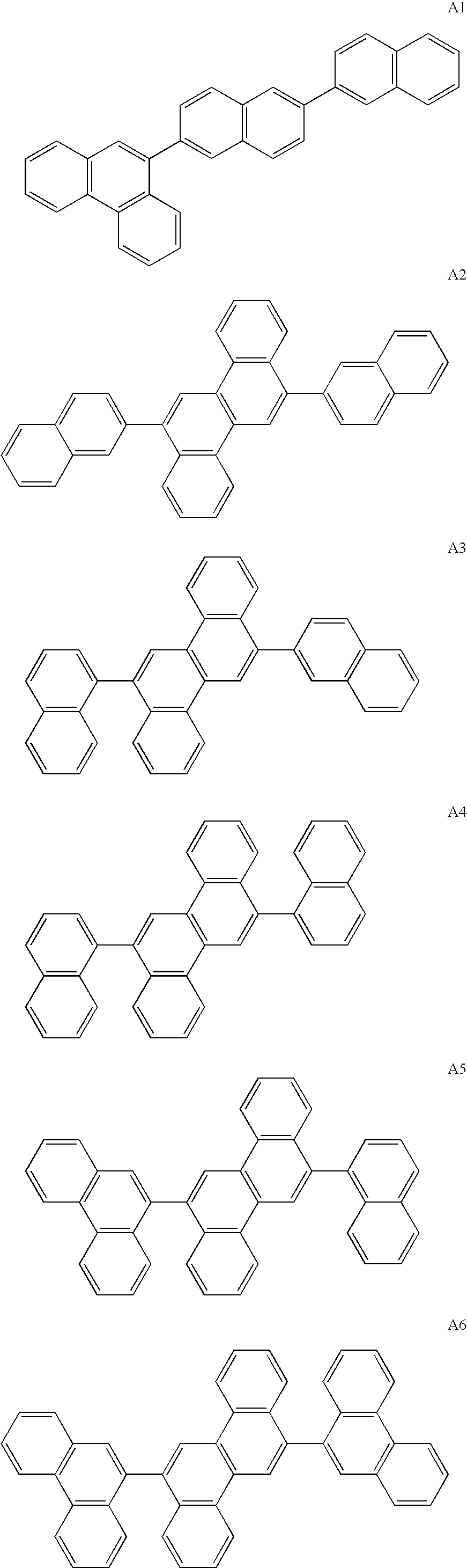
Synthesis of Compound A1
Synthesis of 2-bromo-6-(2-naphthyl)naphthalene
[0250]Under an argon gas atmosphere, 246 g (860 mmol) of 2,6-dibromonaphthalene, 163 g (950 mmol) of 2-naphthalene boronic acid, 20 g (17.0 mmol) of tetrakis(triphenylphosphine)palladium(0), 3 L of dimethoxyethane (DME) and 1.5 L of 2M sodium carbonate solution were mixed, and stirred for 16 hours while being refluxed. After the completion of the reaction, precipitated crystal was separated by filtration. Then, the obtained solid was cleansed with water, methanol and hexane. The obtained solid was dried under reduced pressure, and 197 g of 2-bromo-6-(2-naphthyl)naphthalene was obtained at an yield of 69%.
[0251]Under an argon gas atmosphere, 5.00 g (15.0 mmol) of 2-bromo-6-(2-naphthyl)naphthalene, 3.50 g (15.8 mmol) of 9-phenanthreneboronic acid, 0.87 g (0.750 mmol) of tetrakis(triphenylphosphine)palladium(0), 50 mL of toluene, 50 mL of dimethoxyethane and 22.5 mL of 2M sodium carbonate solution were mixed, and sti...
synthesis example 2
Synthesis of Compound A6
[0252]Under an argon gas atmosphere, 5.00 g (13.0 mmol) of 6,12-dibromochrysene, 6.04 g (27.2 mmol) of 9-phenanthreneboronic acid, 0.75 g (0.65 mmol) of tetrakis(triphenylphosphine)palladium(0), 50 mL of toluene, 50 mL of dimethoxyethane and 40 mL of 2M sodium carbonate solution were mixed, and stirred for 10 hours at 90 degrees C. Subsequently, the reaction mixture was warmed up to room temperature, added with water and stirred for 1 hour. After the solid precipitated during the reaction was separated by filtration, the obtained solid was cleansed with water, methanol, dimethoxyethane and toluene in this order. By dissolving the obtained solid in toluene and refining the solution by silica-gel column chromatography, 4.6 g of the compound A6 was obtained at an yield of 61%.
[0253]Mass-spectrum analysis consequently showed that m / e was equal to 580 while a calculated molecular weight was 580.22.
PUM
| Property | Measurement | Unit |
|---|---|---|
| Nanoscale particle size | aaaaa | aaaaa |
| Nanoscale particle size | aaaaa | aaaaa |
| Energy | aaaaa | aaaaa |
Abstract
Description
Claims
Application Information