Optical recording medium, metal complex compound and organic dye compound

a metal complex and optical recording technology, applied in the field of optical recording mediums, to achieve the effects of reducing the solubility of organic solvents, high density optical information, and high sensitivity

Inactive Publication Date: 2009-02-26
VERBATIM CORPORATION
View PDF14 Cites 19 Cited by
  • Summary
  • Abstract
  • Description
  • Claims
  • Application Information

AI Technical Summary

Benefits of technology

[0032]The optical recording medium applicable to the present invention enables high-density optical information to be written and read in high sensitivity using a short wavelength laser beam.
[0033]A best mode to carry out the present invention (referred to as exemplary embodiment hereinafter) will be detailed below. The present invention is, however, not limited to the following exemplary embodiments and various modifications may be carried out within a scope of the invention. Drawings used are also used only to illustrate the present exemplary embodiments, but not intended to represent an actual size.
[0034]In addition, a monovalent functional group R1 to R10 in the pyridone azo compound represented by the general formulas [I] to [III] may have a substituent as needed. However, the term “substituent” in this case or the term “substituent” involved in “may be substituted” or “may have a substituent” described hereinafter does not include an acidic water soluble group such as carboxyl group, sulfonic acid group and the like. It is not desirable that the water soluble group such as the carboxyl group, sulfonic acid group and the like are included in the pyridone azo compound represented by the general formulas [I] to [III] because its solubility in an organic solvent is reduced. Also, water resistance of the recording layer of the optical recording...

Problems solved by technology

Such recording media suitable for optical writing and reading with use of a relatively long wavelength laser beam have such a prob...

Method used


Image

  • Optical recording medium, metal complex compound and organic dye compound
  • Optical recording medium, metal complex compound and organic dye compound
  • Optical recording medium, metal complex compound and organic dye compound

Examples


first exemplary embodiment

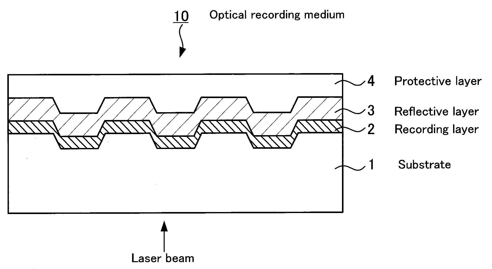
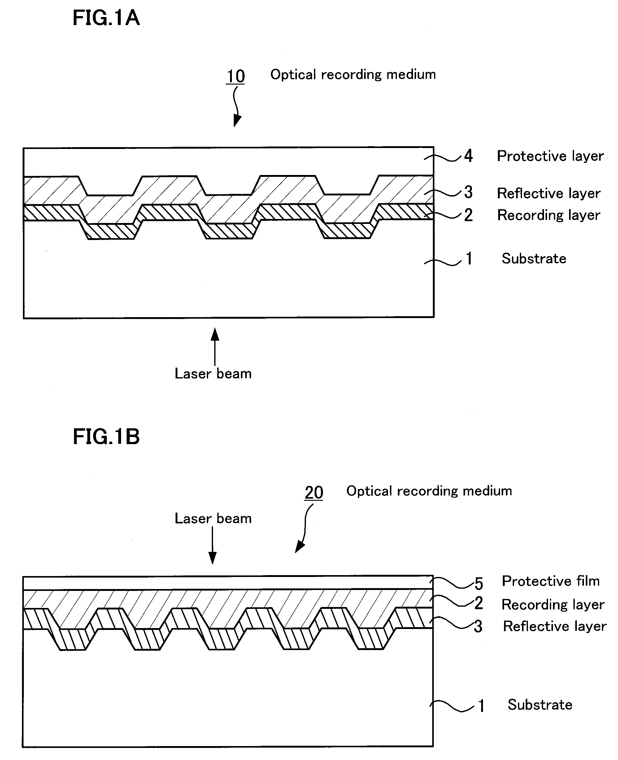
[0097]Optical recording medium 10 shown in FIG. 1A is laminated in turn with a substrate 1 composed of light transmitting material 1, recording layer 2 formed on substrate 1 and reflective layer 3 and protective layer 4 laminated on recording layer 2. Optical recording medium 10 is irradiated with a laser beam from the side of substrate 1 to record and read information.

[0098]In addition, in the optical recording medium 10, for convenience of the explanation, the side on which protective layer 4 is present and the side on which substrate 1 is present are referred to as upside and downside, respectively, and a face of each layer corresponding to these directions is referred to as the upper surface and the lower surface, respectively.

[0099]Various materials can be used as substrate 1 as far as the material is basically transparent at the wavelength of recording light and reading light. Specifically, they include, for example, resins such as acrylic type resins, methacrylic type resins,...

second exemplary embodiment

[0121]Second exemplary embodiment of the optical recoding medium is next described.

[0122]FIG. 1(B) is a figure to describe second exemplary embodiment of the optical recording medium. Common parts with optical recording medium 10 in first exemplary embodiment are given the same reference letters and their explanation is omitted.

[0123]Optical recording medium 20 shown in FIG. 1(B) is laminated with a substrate 1 composed of a light transmitting material, reflective layer 3 provided on substrate 1, recording layer 2 laminated on reflective layer 3 and protective film 5 in this order. Optical recording medium 20 is irradiated with a laser beam from a side of protective film 5 to record and read information.

[0124]Protective film 5 may be laminated with a film or sheet-like material by an adhesive or formed using a similar material to above protective layer 4, to which a coating liquid for film formation is applied, cured and dried. Thickness of protective film 5 is generally 0.1 μm or m...

example 1

(a) Synthetic Example

[0142](a-1)

[0143]In 20 ml of ethanol, 22.63 g (0.2 mol) of ethyl cyanoacetate represented by the following structural formula [1], 26.03 g (0.2 mol) of ethyl 3-oxobutanoate represented by structural formula [2] and 14.63 g (0.2 mol) of n-butylamine represented by structural formula [3] were dissolved, to which 6 ml of piperidine was added dropwise and then the mixture was refluxed with stirring for 26.5 hours. After cooling, the reaction mixture was poured into 200 ml of 10% hydrochloric acid, which was stirred to precipitate solids. The solids separated were collected by filtration, washed with water, then suspended in 100 ml of hexane, stirred for about 30 minutes and then filtered to collect precipitates, which were heated under vacuum to dryness to yield 11.3 g (yield: 27.4%) of the following compound [4] (1-n-butyl-3-cyano-4-methyl-6-hydroxy-2-pyridone).

[0144]In a solution of 30 ml of acetic acid, 10 ml of propionic acid and 2 ml of concentrated sulfuric ac...


PUM


Abstract

Problem: To provide an optical recording medium having a recording layer improved in light stability that is capable of writing and reading of high-density optical information by a short-wavelength laser beam.
Means for Solving the Problems: There is provided an optical recording medium with a recoding layer comprising an organic dye compound, wherein the recording layer contains a metal complex compound composed of a pyridone azo compound represented by the following the general formulas [I] to [III] and a divalent ion of metal coordinated to it such as nickel, cobalt, iron, zinc, copper, manganese and the like, wherein the pyridone azo compound contains a 6-hydroxy-2-pyridone structure as a coupling component and isoxazole, 1,2,4-triazole or pyrazole structure as a diazo component.
(In the general formulas [I] to [III], R1 to R10 each is independently a hydrogen atom or monovalent functional group.)

Description

TECHNICAL FIELD[0001]The present invention relates to an optical recording medium and the like, in more detail, an optical recording medium and the like relative to a blue laser beam improved in light stability.BACKGROUND ART[0002]Various optical recording media such as CD-R / RW, DVD-R / RW, MO and the like are widely accepted and used as an external memory device for an information processing equipment such as a computer and the like, since a large capacity of information can be stored and easily and randomly accessed. Among them, an organic dye type optical recording medium provided with a recording layer containing an organic dye compound as represented by CD-R and DVD-R is considered to be superior in terms of a low cost and its easiness manufacturing.[0003]On the other hand, an increase of the amount of information handled has requested an increase of a recording density in a medium and a high density writable and readable optical recording medium has been proposed for use of a la...

Claims


Application Information

Patent Timeline
IPC IPC(8): G11B3/70C07F15/04
CPCC09B29/3634G11B2007/25417C09B45/18C09B45/20G11B7/2463G11B7/2467G11B7/248G11B7/2492G11B7/2531G11B7/2532G11B7/2534G11B7/2535G11B7/2536G11B7/2542G11B7/2548G11B7/259C09B45/14C07F15/04G11B7/244
Inventor MIYAZAWA, TAKASHIKUROSE, YUTAKA
Owner VERBATIM CORPORATION
Why Eureka
Try Eureka