
Optical pulse sources

Active Publication Date: 2009-04-16
NKT PHOTONICS
View PDF15 Cites 75 Cited by
  • Summary
  • Abstract
  • Description
  • Claims
  • Application Information

AI Technical Summary

Benefits of technology

[0010]The optical pulse source enables optical supercontiuum pulses to be generated with flexible control of the output pulse repetition rate, and thus the pulse-to-pulse separation. Control of the inter-pulse separation is of particular advantage where the source is used to provide supercontinuum illumination in applications where decay lifetimes are measured, such as FLIM, and the optical pulse source can be operated to generate supercontiuum pulses at pulse repetition rates of less than 20 MHz for such applications.
[0017]Preferably, a single wavelength-tunable optical bandpass filter is configured to perform both wavelength filtering and pulse-picking. The second gating device is preferably further operable to reduce the optical intensity of one or more optical pulses in the pulse set or train. The second gating device can thereby be operated to control the optical intensity of the pulses in a train of optical pulses of different wavelengths, so that the optical intensity can be changed for pulses of different wavelengths.
[0019]According to a second aspect of the present invention there is provided a method of scaling the energy of optical supercontinuum pulses generated using the optical pulse source as described above. The method comprises the steps of: reducing the pump pulse repetition rate of the optical pump laser; and increasing the pump pulse duration. This invention therefore enables the development of higher-energy supercontinuum pulse sources for certain applications where higher pulse intensity is required, with STED microscopy being one example.
[0021]According to a third aspect of the present invention there is provided an illumination source for stimulated emission depletion microscopy. The illumination source comprises an optical pulse source as described above, configured to generate output optical pulses having a repetition rate in the range 1 MHz to 10 MHz and an energy spectral density of at least 100 picojoules per nanometer (pJ / nm), the optical pulse source being operated to scale the energy of the optical supercontinuum pulses by reducing the pump pulse repetition rate of the optical pump laser and increasing the pump pulse duration.
[0024]In conventional STED microscopes (see, e.g., G. Donnert et al., Proceedings of the Natural Academic Society U.S.A 103,11440-11445 (2006)) two lasers are used simultaneously, one (typically a Ti:Sapphire laser) with high optical intensity to form the STED beam and a second tunable visible laser to excite the fluorescence. Conventional supercontinuum lasers, based on modelocked fiber laser-pumped PCF's or Ti:Sapphire laser-pumped PCF's, are too low in pulse energy for STED. Using a reduced repetition rate and longer pulse according to the present invention, an optical pulse source is provided which is operable to generate supercontinuum pulses having a pulse energy spectral density approaching 1 nJ / nm, making this a suitable single-source solution for both fluorescence excitation and STED within a STED microscope.
[0025]Another benefit of this invention is that it provides the ability to be flexible in pump pulse duration and the length of microstructure optical fiber required to generate the supercontinuum output pulses.

Problems solved by technology

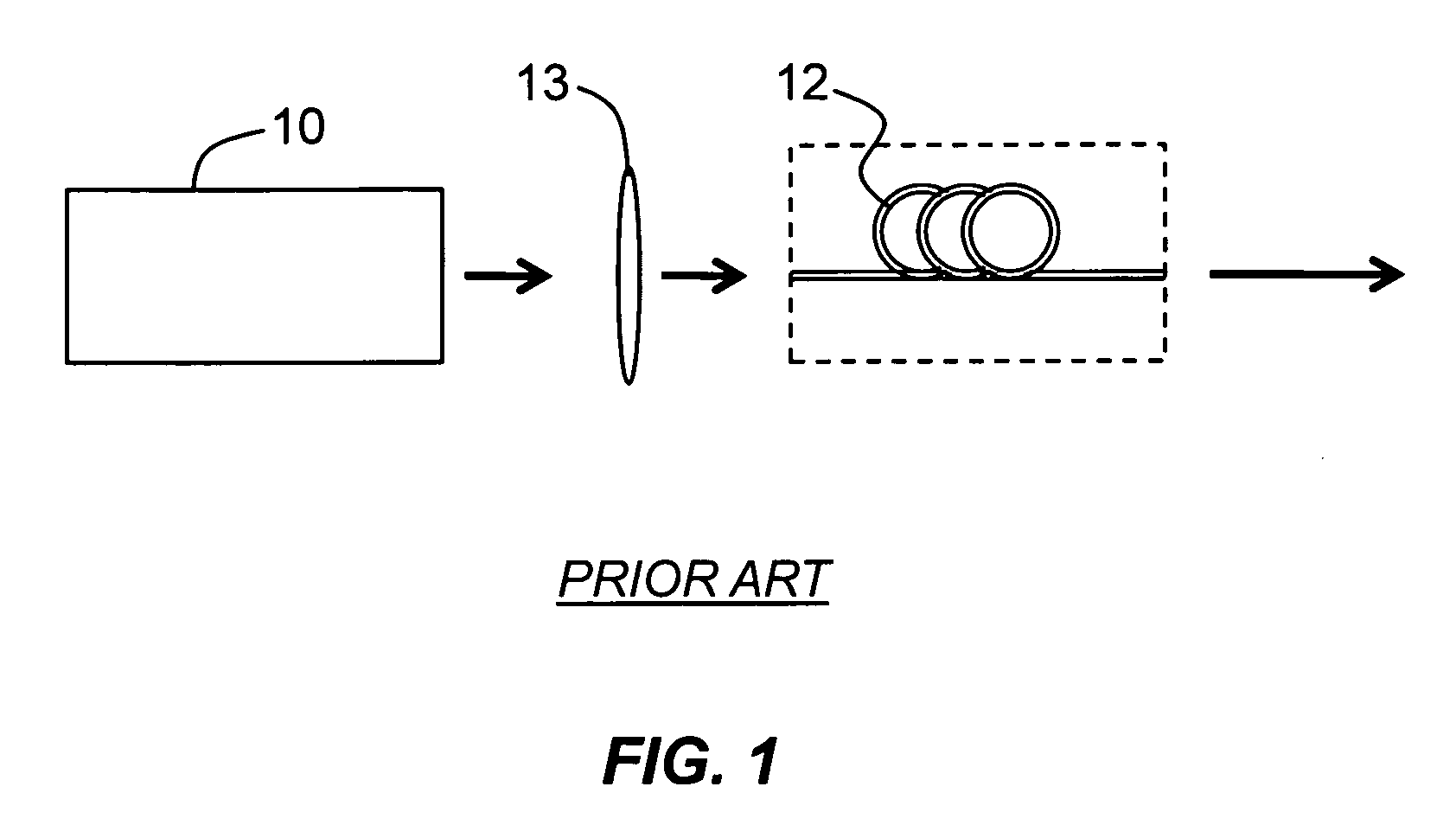
However, often, the high repetition rates can be a limiting factor in lifetime imaging, where the pulse-to-pulse separation (50 ns for a 20 MHz source, down to a few nanoseconds for a 160 MHz source) can be much shorter than the lifetime of the sample under evaluation.
Repetition rates of less than 20 MHz, while not impossible to achieve, are difficult to deliver from a mode-locked fiber oscillator due to high nonlinearity within a long cavity (10 m for a 10 MHz oscillator).
From a DPSS source, such a cavity (5 m long for 20 MHz and 100 m in length for 1 MHz) is almost impossible to make due to the required complexity of the cavity design.

Method used


Image

  • Optical pulse sources
  • Optical pulse sources
  • Optical pulse sources

Examples


first embodiment

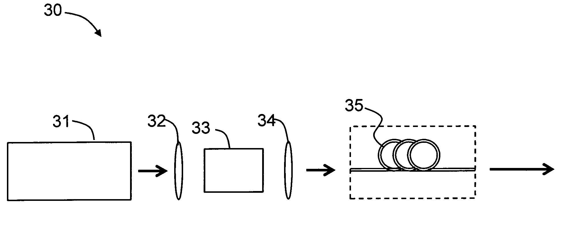
[0037]Referring to FIG. 3, the invention provides an optical pulse source 30 comprising an optical pump laser source 31, a microstructured optical fiber 35 and a gating device 33 (also referred to below as “gating means”33).

[0038]The optical pump laser 31 in this example takes the form of a diode pumped solid state (DPSS) laser source (for example a mode-locked 1064 nm laser operating at 76 MHz), which is operable to produce pulses of approximately 200 nJ energy and duration 10 ps. The output pulses from the pump laser 31 pass through lens (e.g., a set of lenses) 32 to the gating means 33, which here comprises an optical modulator, synchronised to the pump laser 31 and operable so that it can gate the pump pulses and produce a pulse train having a reduced repetition rate (Rr), where Rr=Rf / N, where Rf is the pump laser fundamental frequency (in this example 76 MHz) and N is a positive integer. The pulses output from the modulator gating device 33 are injected via optics 34 into the m...

fifth embodiment

[0059]In the invention, the use of a fiber laser incorporating a pulse-picker element allows for the delivery of higher energy supercontinuum lasers within the visible region of the spectrum.

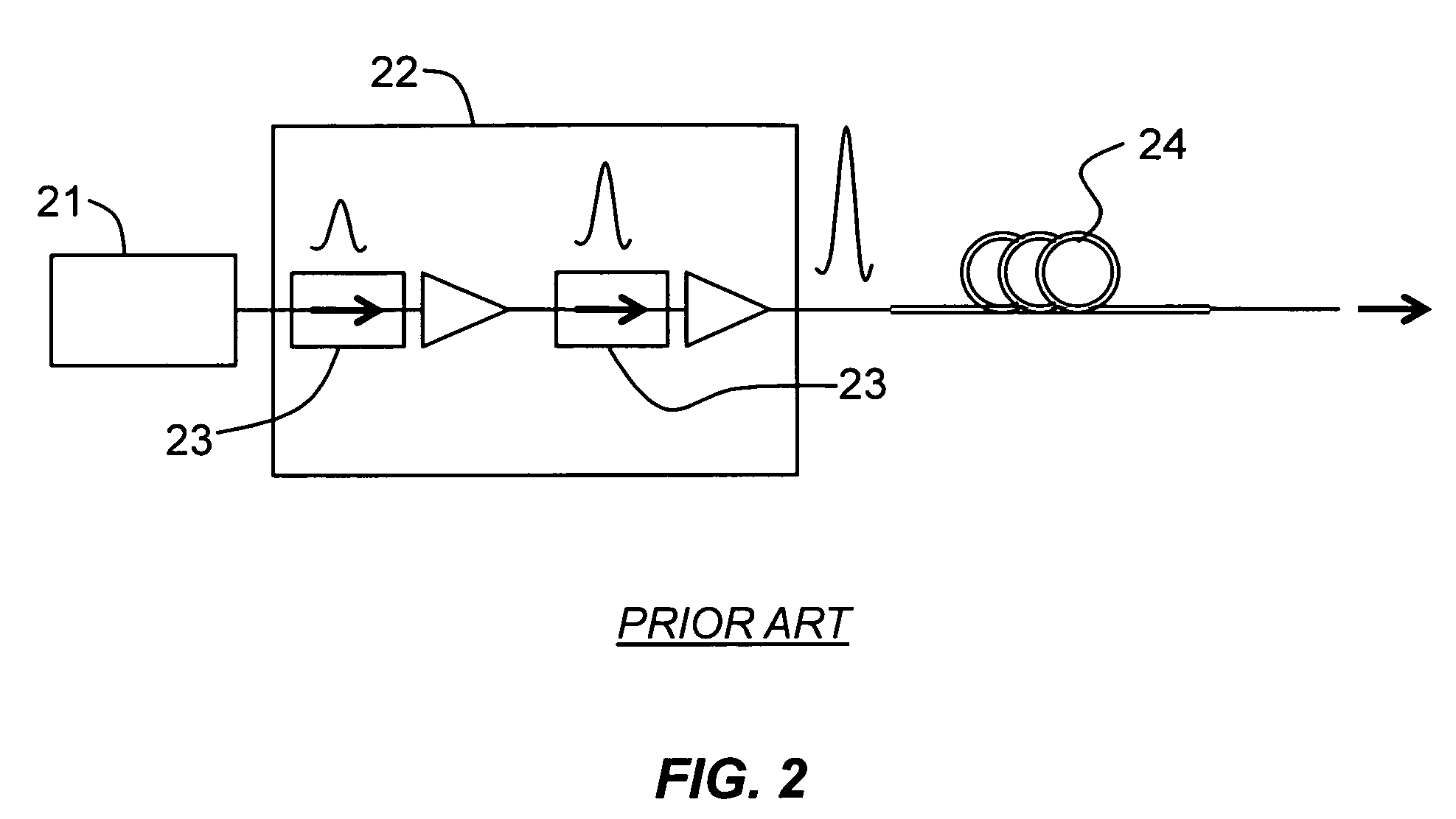
[0060]In some examples, it is important to be able to scale the energy from the supercontinuum optical pulses—particularly within the visible region of the spectrum. Using the same system configuration as FIG. 4, it is possible to scale the average supercontinuum energy by reducing the pump pulse repetition rate but increasing the pump pulse duration to hundreds of picoseconds. This effectively results in a higher energy 1064 nm fundamental input pulse (the peak power of the pulse is limited within the fiber amplifier by nonlinear interactions dominated by stimulated Raman scattering (SRS)) and a corresponding increase in the average output supercontinuum pulse energy across the supercontinuum spectra exiting the PCF.

[0061]By increasing the pulse duration, one therefore increases the average pul...

sixth embodiment

[0065]the invention comprises a pulse-picked optical pulse source 40, as shown in FIG. 6, in which the pump pulse repetition rate is reduced to 1 MHz, and the pulse duration increased to approximately 200 ps. In order to generate the required spectral broadening within the PCF 44, 40 KW of pulse peak power is attained from the pulsed pump source 41 at an average output power of 8 W, resulting in a 2 W supercontinuum, with 1 mW / nm power spectral density in the visible spectral region, corresponding to approximately 1 nJ / nm energy spectral density.


PUM


Abstract

An optical pulse source comprising a DPSS pump laser, a photonic crystal fiber (PCF), and acousto-optic modulator (AOM) gating device is disclosed. The pump pulses are coupled through lenses to the AOM gating device, which is synchronized to the pump laser and is operable to gate the pump pulses to a reduced repetition rate Rr=Rf / N, where Rf is the pump laser fundamental frequency. The pulses from the AOM are injected via optics into the PCF. Propagation through the PCF causes the pulses to broaden spectrally to produce optical supercontinuum pulses. An optical pulse source that further includes an acousto-optical tunable filter (AOTF) operable to convert the optical supercontinuum pulses into wavelength variable output pulses is also provided. A method of scaling the energy of the optical supercontinuum pulses is also disclosed.

Description

CROSS-REFERENCE TO RELATED APPLICATIONS[0001]This application claims the benefit of priority under 35 U.S.C. § 119 of Great Britain (GB) Patent Application Ser. No. 0800936.7, filed in the United Kingdom on Jan. 19, 2008, which application is incorporated by reference herein.FIELD OF THE INVENTION[0002]The present invention relates to an optical pulse source, and an illumination source for a Stimulated Emission Depletion (STED) microscope including the optical pulse source.BACKGROUND ART[0003]Supercontinuum lasers delivering continuous spectra over an ultra-broad bandwidth offer an ideal source for many applications within biomedical imaging, component characterisation, manufacturing control and defense research. The most common form of supercontinuum laser comprises an ultrashort pulse optical pump source operating at a pump wavelength in the Infra-Red (IR) region of the spectrum (typically around 800 nm for a Ti:Sapphire laser or 1064 nm for mode-locked fiber lasers and diode pump...

Claims


Application Information

Patent Timeline
IPC IPC(8): H01S3/10
CPCG01N21/6458G01N2021/6419G01N2021/6441G01N2201/0697G02B21/16G02F1/353H01S3/108G02F2001/3528H01S3/11H01S3/2308H01S3/10H01S3/10046H01S3/1024G02F1/365G02F1/3528H01S3/0092H01S3/1106H01S3/0085
Inventor CLOWES, JOHNGRUDININ, ANATOLYGODFREY, IAN
Owner NKT PHOTONICS
Learn More