
DNA microarray having hairpin probes tethered to nanostructured metal surface

a nanostructured metal surface and hairpin technology, applied in the direction of fluorescence/phosphorescence, instruments, nucleotide libraries, etc., can solve the problems of hairpin unfolding, signal generation, time-consuming and laborious, and achieve optimal performance, fluorescence enhancement, avoid or minimize the need for spacer molecules

Inactive Publication Date: 2009-05-28
UNIVERSITY OF ROCHESTER
View PDF10 Cites 33 Cited by
  • Summary
  • Abstract
  • Description
  • Claims
  • Application Information

AI Technical Summary

Benefits of technology

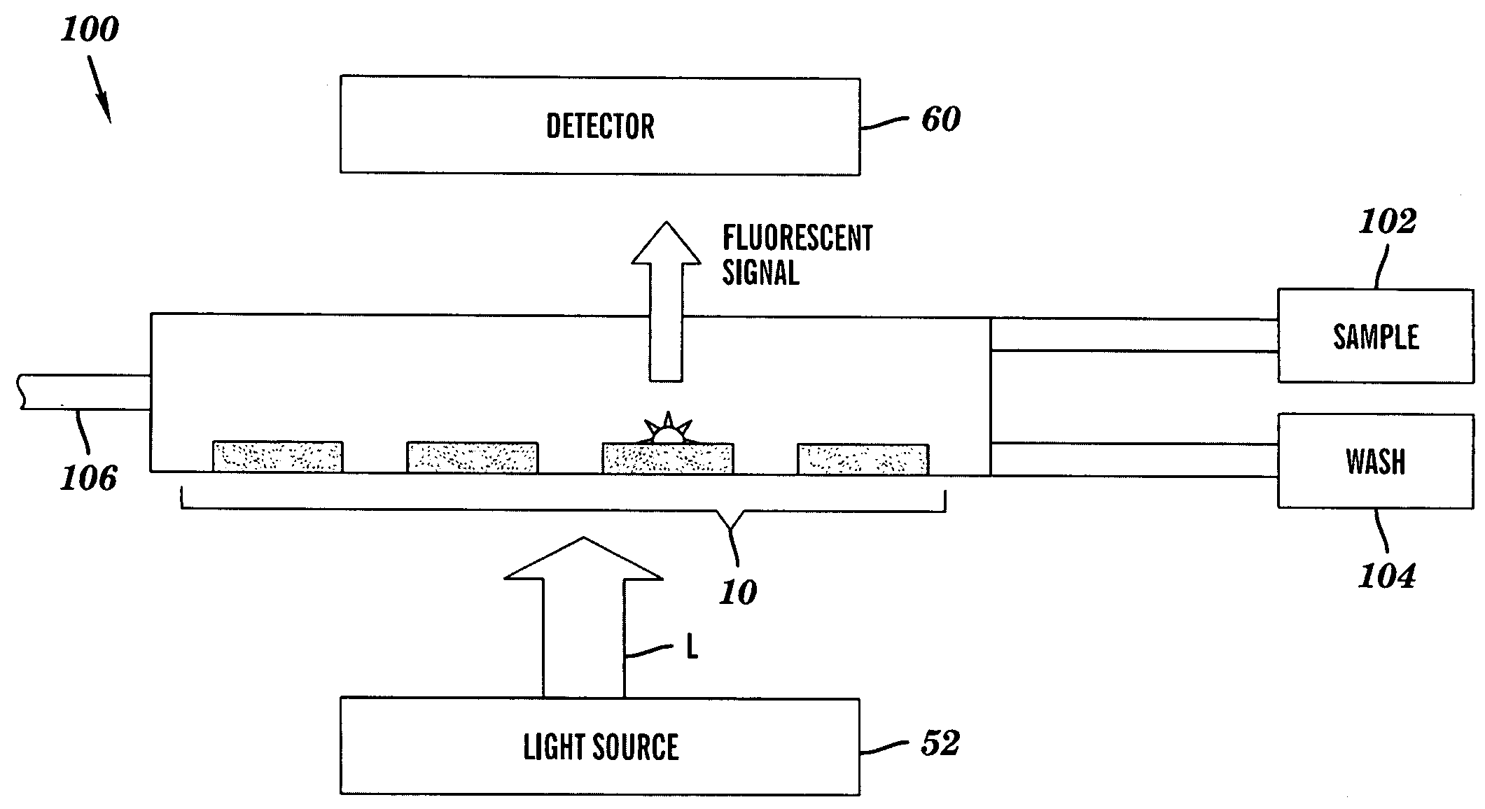
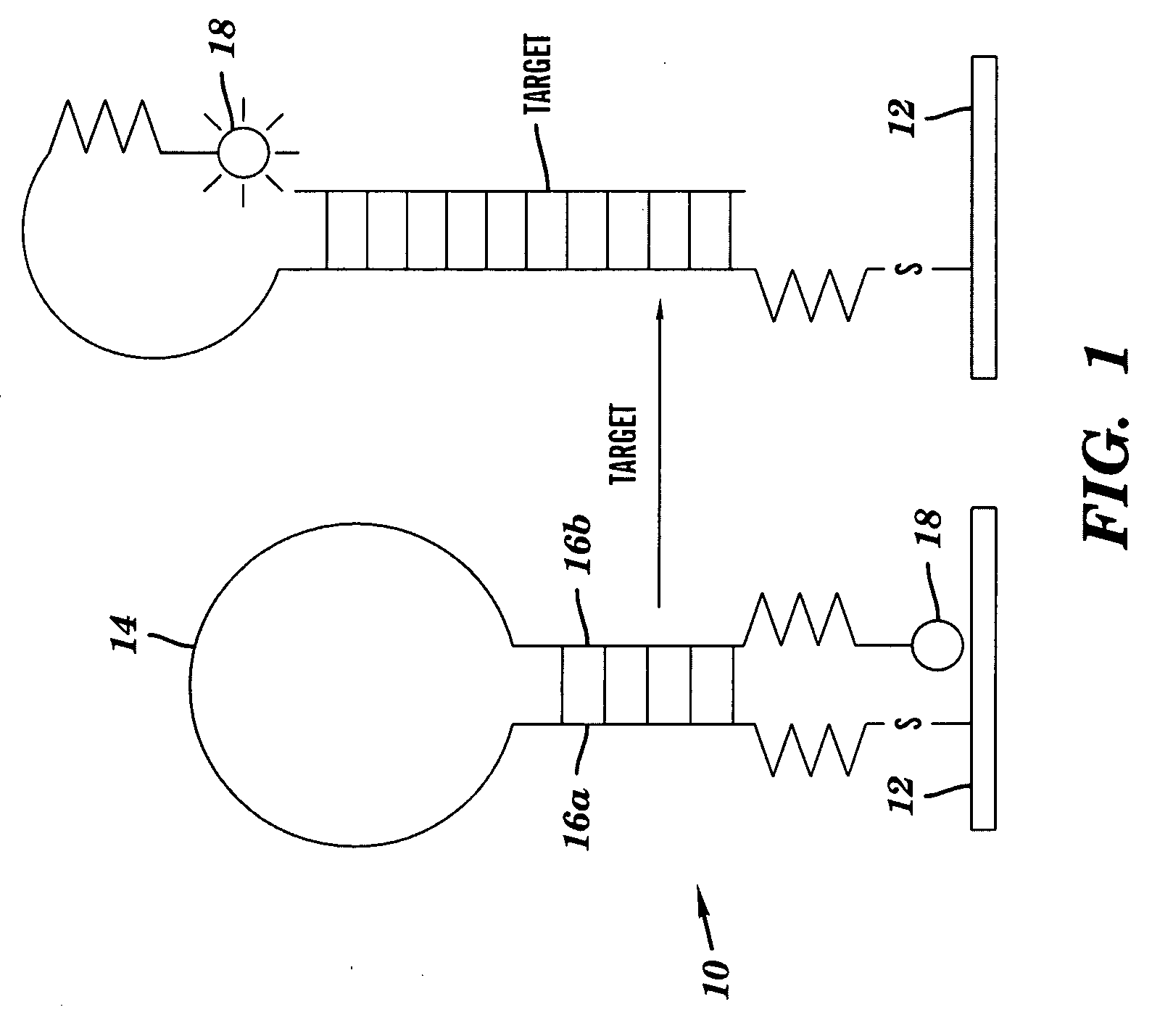
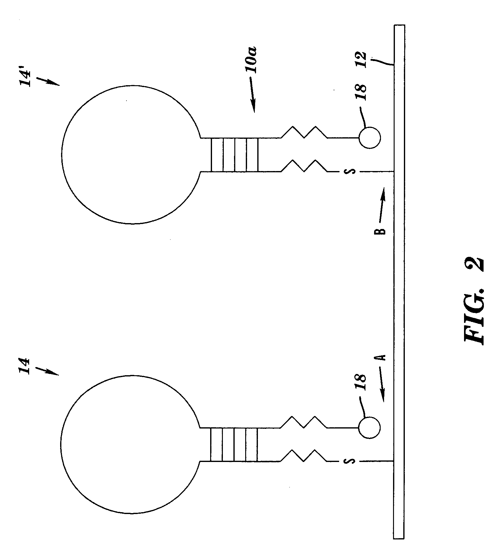
[0008]A first aspect of the present invention relates to a sensor chip that includes: a substrate, at least a portion of which is covered by a metal nanoparticle film; a first nucleic acid molecule that is characterized by being able to (i) self-anneal into a hairpin conformation and (ii) hybridize specifically to a target nucleic acid molecule, the first nucleic acid molecule having first and second ends, which first end is tethered to the metal nanoparticle film; and a first fluorophore bound to the second end of the first nucleic molecule. When the first nucleic acid molecule is in the hairpin conformation, the metal nanoparticle film substantially quenches fluorescent emissions by the first fluorophore, and when the first nucleic acid molecule is in a non-hairpin conformation fluorescent emissions by the first fluorophore are surface plasmon-enhanced.
[0012]The present invention affords self-labeled nucleic acid detection systems that are capable of achieving a dramatic (˜10-fold) fluorescence enhancement over detection systems that utilize a planar Au quenching surface. The examples presented herein demonstrate that the surface topography of the quenching nanoparticle substrate and the amount of Ag that was deposited onto the surface can be varied by controlling the Ag exposure time in a constant concentration of AgNO3 solution. Furthermore, detection performance and signals were dependent on both the surface topography / NP coverage and the distance between the fluorophore and the Ag substrate surface. These findings collectively indicated the importance of local probe density adjustment and probe length selection for detection performance. The ability to pattern the probe immobilization on the surface by controlling the spacing between nanoparticles can avoid or minimize the need for spacer molecules that are required for optimal performance on solid Au surfaces. Of further interest is the fact that the low-exposure nanoparticle substrates are transparent, which should allow for their inclusion in a flow-through device in which either imaging or illumination occurs from the opposite face rather than the functionalized face that is exposed to the sample.

Problems solved by technology

124:2096-2097 (2002), since that increases the time, cost, and potential for error inherent in the analysis.
Addition of the target sequence leads to hairpin unfolding, concomitant duplex formation, and signal generation.
Using the substrate itself as the quenching agent significantly decreases the complexity of the synthetic DNA probe hairpin, because attachment of a separate quencher is unnecessary.
Simply increasing the intensity of the excitation source is not a viable route to increased signals, because many fluorescent labels will photobleach completely within a fraction of a second for high excitation powers.
For example, because rhodamine—comparatively a very photostable dye—photobleached at I˜1 kW / cm2, it is highly unlikely that changing dyes will improve the signal.
An additional limitation arises when using metal films as quenching surfaces for fluorophore-functionalized DNA hairpin probes.

Method used


Image

  • DNA microarray having hairpin probes tethered to nanostructured metal surface
  • DNA microarray having hairpin probes tethered to nanostructured metal surface
  • DNA microarray having hairpin probes tethered to nanostructured metal surface

Examples


example 1

Fabrication and Characterization of Nanostructured Ag Substrates

[0095]Fabrication of nanostructured Ag substrates was accomplished by covalently attaching Ag nanoparticles onto 3-mercaptopropyl-trimethoxysilane (MPTS, Gelest, Inc) treated glass chips via Ag+ ion reduction in N—N dimethylformamide (DMF, Mallinckrodt) (Pastoriza-Santos et al., Langmuir 15:948-951 (1999); Pastoriza-Santos et al., J. Colloid Interface Sci. 221:236-241 (2000); Sabanayagam et al., Nucleic Acids Res. 35(2):e13 (2007), each of which is hereby incorporated by reference in its entirety. First, a standard glass microscope slide was cleaned by soaking with piranha solution (H2SO4: 35%: H2O2; 3:1) for 15 minutes. The glass slide was then rinsed with distilled, deionized (DDI) water, soaked in a 10 M NaOH solution for 5 minutes, rinsed again with DDI water, and finally dried under nitrogen gas. The cleaned glass slides were silanized by incubating in a solution composed of 1% MPTS, 95% methanol, and 4% 1 mM aceti...

example 2

DNA Detection System Utilizing Nanostructured Ag Substrates as the Sensing Substrates

[0099]To examine the correlation between the relative intensity change and the substrate surface characterization, the detection performance on nanostructured Ag substrates fabricated under different Ag exposure times in a 10 mM AgNO3 solution was examined.

[0100]This experiment employed the previously described probe designated BaPag 1208, which has the nucleotide sequence 5′-TCGTTAGTGTTAGGAAAAAATCAAACACTCGCGA-3′ (SEQ ID NO: 1). The probe was purchased from Integrated DNA Technologies, Inc (IDT); this probe bears a 3′-tetramethyl rhodamine (TMR) fluorophore (Abmax: 559 nm, Emmax: 583 nm) and a 5′-thiol (disulfide form)). This probe has a secondary structure as described in U.S. Patent Publ. No. 20070166731, which is hereby incorporated by reference in its entirety. Use of this probe permitted the comparison of Ag NP substrate results with prior experiments where planar Au films were used as the sens...

example 3

Role of Surface Blocking Agent with Ag Nanoparticle Film

[0109]Earlier studies with planar Au substrate demonstrated the importance of adding a surface blocking agent, mercaptopropanol, as a competitive spacer molecule between probe DNA to mitigate the steric effect (Du et al., J. Am. Chem. Soc. 127:7932-40 (2005), which is hereby incorporated by reference in its entirety). To find out if the finding still holds in the new nanoparticles films, the effect of MP concentration on detection performance was examined. In this experiment, the ratio of [MP] / [DNA] was varied from 0 to 25 ([DNA] represents probe DNA concentration, which was held constant at 300 nM). Lowering the ratio of [MP] to [DNA] from 1 with the use of Au planar substrates resulted in poor performance; specifically, high background signals were measured (Du et al., J. Am. Chem. Soc. 127:7932-40 (2005), which is hereby incorporated by reference in its entirety). Surprisingly, the opposite results were observed with the use...


PUM

PropertyMeasurementUnit
Thicknessaaaaaaaaaa
Surface roughnessaaaaaaaaaa

Abstract

A sensor chip and detection device are disclosed. The sensor chip includes a substrate, at least a portion of which is covered by a metal nanoparticle film; a first nucleic acid molecule that is characterized by being able to (i) self-anneal into a hairpin conformation and (ii) hybridize specifically to a target nucleic acid molecule, the first nucleic acid molecule having first and second ends, which first end is tethered to the metal nanoparticle film; and a first fluorophore bound to the second end of the first nucleic molecule. When the first nucleic acid molecule is in the hairpin conformation, the metal nanoparticle film substantially quenches fluorescent emissions by the first fluorophore, and when the first nucleic acid molecule is in a non-hairpin conformation fluorescent emissions by the first fluorophore are surface plasmon-enhanced.

Description

[0001]The present application claims the priority benefit of U.S. Provisional Patent Application Ser. No. 60 / 985,459, filed Nov. 5, 2007, which is hereby incorporated by reference in its entirety.FIELD OF THE INVENTION[0002]The present invention relates to hybridization-based biosensors containing hairpin probes and their use in identifying target nucleic acids in samples.BACKGROUND OF THE INVENTION[0003]Recent intense interest in the use of rapid genetic analysis as a tool for understanding biological processes (Wodicka et al., J. Nat. Biotechnol. 15:1359-1367 (1997); Iyer et al., Science 283:83-87 (1999)), in unlocking the underlying molecular causes of disease, and in the development of biosensors, has led to a need for new sensitive and arrayable chip-based analytical tools. Of high importance is the need for techniques that do not require labeling of the target sample (Sando et al., J. Am. Chem. Soc. 124:2096-2097 (2002), since that increases the time, cost, and potential for e...

Claims


Application Information

Patent Timeline
IPC IPC(8): C40B30/04C40B40/08C40B50/18C40B60/12
CPCB01J19/0046G01N21/6428B01J2219/00576B01J2219/00596B01J2219/00605B01J2219/00612B01J2219/00626B01J2219/00637B01J2219/00648B01J2219/00659B01J2219/00702B01J2219/00722B82Y30/00C12Q1/6825C40B50/18C40B60/08B01J2219/00527G01N21/05G01N21/64C12Q2525/301
Inventor MILLER, BENJAMIN L.KRAUSS, TODD D.ROTHBERG, LEWIS J.PENG, HSIN-I
Owner UNIVERSITY OF ROCHESTER
Learn More