
Stainless Steel, Titanium, or Titanium Alloy Solid Polymer Fuel Cell Separator and Its Method of Produciton and Method of Evaluation of Warp and Twist of Separator

a solid polymer fuel cell and separator technology, applied in the direction of cell components, sustainable manufacturing/processing, instruments, etc., can solve the problems of obstructing greater compactness, high cost, and development of breakage-resistant carbon-based separators, so as to reduce the cost and mass productivity, reduce the electromotive force, and reduce the cost

Active Publication Date: 2009-09-10
SINTOKOGIO LTD
View PDF2 Cites 29 Cited by
  • Summary
  • Abstract
  • Description
  • Claims
  • Application Information

AI Technical Summary

Benefits of technology

[0044]In consideration of the state of the prior art, the present invention has as its object the provision of a solid polymer fuel cell separator comprised of stainless steel, titanium, or a titanium alloy having a surface layer part to which conductive substance particles are fixed, where, at the time of use of the fuel cell, there is little drop in the electromotive force due to deterioration of the contact resistance of the separator surface and deterioration of the cell properties, the contact resistance of the separator surface with the carbon paper is low, and furthermore the flatness for stacking is superior, and its method of production. That is, the present invention has as its object the simultaneous solution of the two problems of the discovery of conductive substances with extremely small ion release and flatness of the separator member shape after treatment and thereby, when making the metal separator for a solid polymer fuel cell a stainless steel alloyed with 11 mass % or more of Cr or titanium or a titanium alloy, securing lower cost and mass productivity by using a material having a high workability to form complicated shapes with a high productivity, then using an inexpensive blast process to drive conductive substances into the metal separator member surface.
[0065]According to the present invention, when using the solid polymer fuel cell, the conductive substance particles fixed to the stainless steel separator surface layer part, titanium separator surface layer part, or titanium alloy separator surface layer part are ones with a low ion release property and further preferably can prevent the formation of oxides at the surfaces of the conductive substance particles after ion release. Therefore, it becomes possible to provide a stainless steel or titanium or titanium alloy solid polymer fuel cell separator having a contact resistance with carbon paper of a low 15 mΩcm2 or less at a surface pressure of 1 MPa, having little deterioration of the low contact resistance at the time of use and resultant drop of the electromotive force, and having flatness sufficient for use for stacking fuel cells.
[0066]Fuel cell cars, fuel cell mobile PCs, and furthermore cogeneration using fuel cells etc. are expected to spread in the future. For their general application, sharp reductions in the costs of the component members are essential. The invention of the present application enables the production of a high performance stainless steel, titanium, or titanium alloy flat separator at a low cost.

Problems solved by technology

As the material for forming a solid polymer fuel cell operating in a region of 150° C. or so or less, a carbon-based material is being used due to the reasons that the temperature is not that high, corrosion resistance and durability can be sufficiently exhibited under that environment, etc., but due to the issue of brittleness, it cannot be made thin and therefore it obstructs greater compactness.
Furthermore, breakage-resistant carbon-based separators are also being developed, but these are expensive cost-wise.
However, in these, the avoidance of cracking or warping by stabilization of the working process and the further reduction of costs in measures for reducing the electrical contact resistance of the surface remained as problems for commercialization.
In stainless steel, titanium, or titanium alloy separators, the contact resistance with the carbon paper forming the current collectors is large, so causes a large drop in the energy efficiency of the fuel cell.
This has been pointed out as a problem.
However, these all take the form of using a precious metal to lower the contact resistance.
However, this method requires too much time for the annealing process of the stainless steel and is liable to reduce the productivity and to increase the costs.
Conversely, if shortening the annealing time to lower the costs, metallurgically chrome-deficient layers are liable to form around the precipitated chrome carbides and lower the corrosion resistance.
Furthermore, working the separator requires a strong working process, so if a large amount of chrome carbides precipitate in the metal structure before working, cracks are liable to occur during the working process.
This method requires time and effort for the process of heating in a nonoxidizing atmosphere to 300 to 1100° C. to break down and eliminate the film ingredients, so is liable to increase the costs.
As a result of tests to reproduce this, there was the problem that a low contact resistance state could not be stably realized.
In this way, development of technology for producing metal separators utilizing the expression of corrosion resistance by a passivation film of stainless steel or titanium or titanium alloy, greatly reducing the contact resistance, and enabling even complicated working and enabling production at a low cost is extremely difficult at present.
Due to this situation, as a practical problem, stainless steel or titanium or titanium alloy first of all basically require productivity and workability being stressed in the material design and production process design.
However, in measures for reducing the electrical contact resistance of the surface, further reduction of the cost is an issue which must be solved for commercialization.
This current mainstream method is criticized as having problems in terms of costs or resources.
The yield of the coated substance unavoidably drops, so the costs are liable to increase.
However, in general, solid polymer fuel cells have a low output voltage per cell of a low 1V or so, so to obtain the desired output, often a large number of fuel cells are stacked and used as stacked fuel cells.
For this reason, in the method of fixing hard fine powder having conductivity on the surface of a base material by shot etc., it is necessary to suppress the occurrence of warping or strain at the separators and set the conditions and perform post-treatment to obtain separators having a good flatness enabling stacking of the fuel cells, but with this method, there are the problems that the separators will deform after shaping and not be able to be stacked.
Commercialization is not possible so long as the optimal conditions are not found.
In this method, a precious metal is used, so without further reduction of the costs, commercialization is not possible.
However, with this method, there was the problem that the separators deformed after shaping and could not be stacked.
However, in these as well, no improvement in the cell performance can be expected without low cost, low electrical contact resistance surface treatment.
However, in the latter, if members are exposed to the corrosive environment in solid polymer fuel cells, at least the conductive substances are liable to be corroded, release ions, contaminate the MEA (composite of solid polymer electrolyte film and electrode), and lower the power generating ability of the fuel cells.

Method used

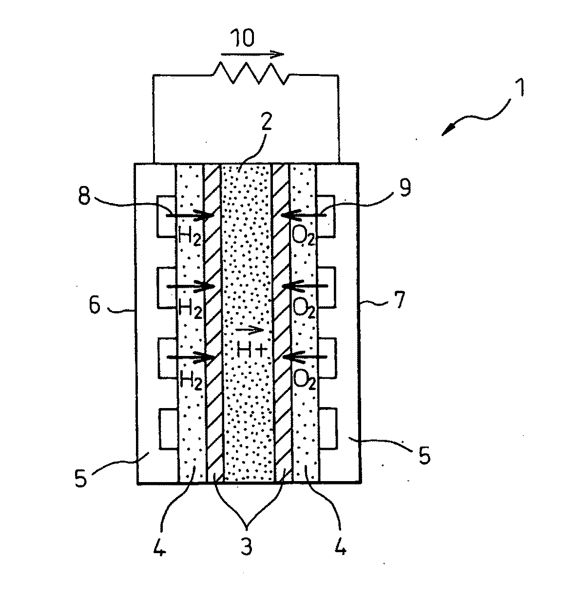
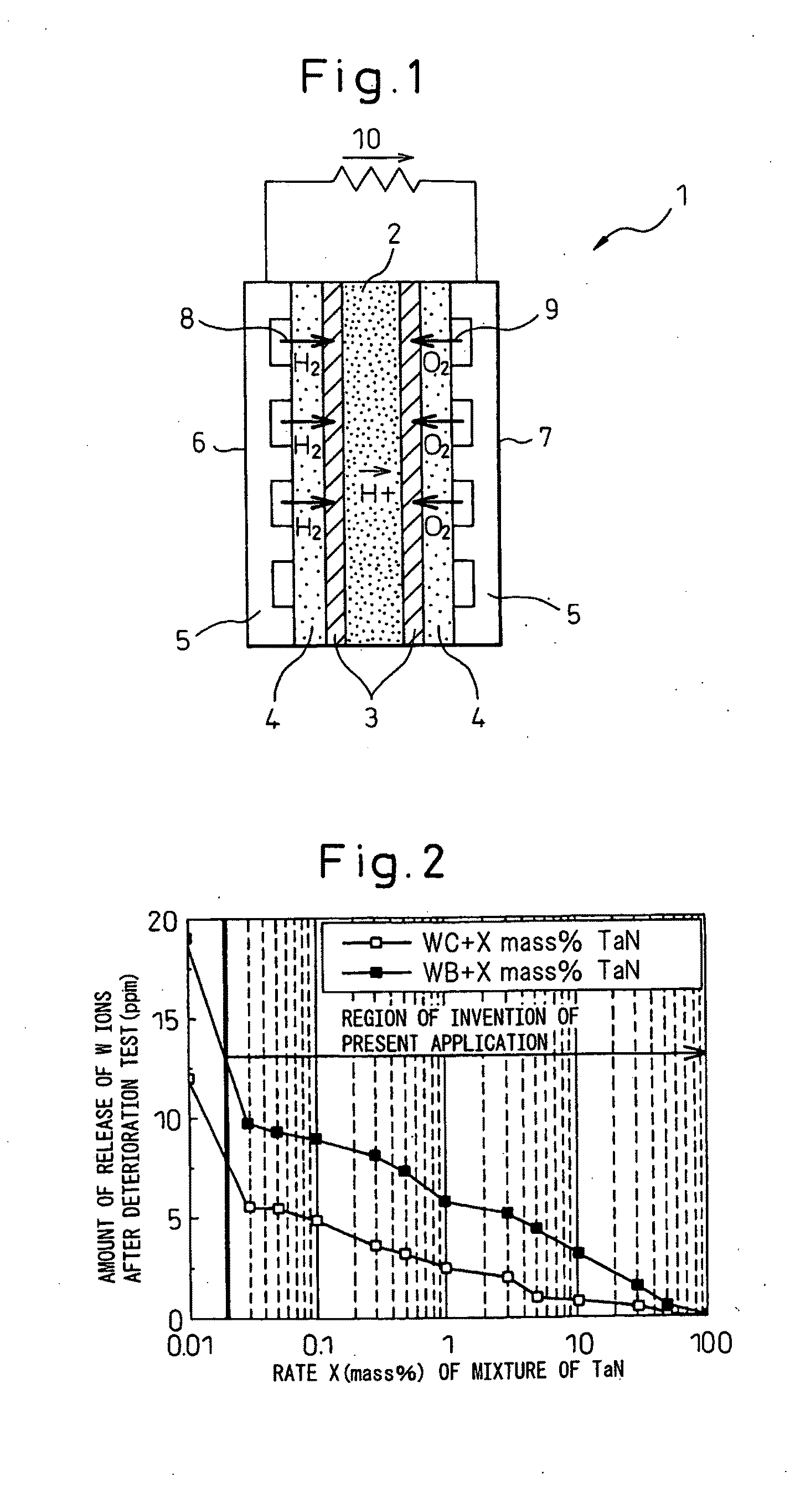

Image

  • Stainless Steel, Titanium, or Titanium Alloy Solid Polymer Fuel Cell Separator and Its Method of Produciton and Method of Evaluation of Warp and Twist of Separator
  • Stainless Steel, Titanium, or Titanium Alloy Solid Polymer Fuel Cell Separator and Its Method of Produciton and Method of Evaluation of Warp and Twist of Separator
  • Stainless Steel, Titanium, or Titanium Alloy Solid Polymer Fuel Cell Separator and Its Method of Produciton and Method of Evaluation of Warp and Twist of Separator

Examples


examples

[0182]Below, examples will be used to explain the present invention in detail.

Example (1) to Example (20)

[0183]The means of the invention were used to treat stainless steel, titanium, or titanium alloy metal separators given surface relief shapes forming gas channels in 100 mm square regions and having flat parts at the four peripheries. Each material had an extremely thin sheet thickness of about 0.1 mm and is easily deformed by a relatively weak force. The stainless steel separators were shaped by rolling, while the titanium and titanium alloy separators were shaped by press forming.

[0184]Table 2 to Table 21 (Example (1) to Example (20)) also include comparative products. Examples of invention products of flat separators treated to become conductive by the blast method according to the invention of the present application are listed. By way of reference, the levels of inclusion of impurity elements in products of the present invention were all levels below the detection limit by e...

example

(20)

[0217]

TABLE 21ContactBuriedresis-Con-tanceConduc-duc-Rough-withIontiveWork-iveTwistnesscarbonreleasesub-Mater-ingsub-Warp rateratepro-paperresis-tanceRe-ClassNo.ialmethodstanceWL1WL2WC1WC2WXCTXLTXCvision(mΩcm2)tancecostmarksInven-86TitaniumPress-TaN:0.010.020.010.010.020.010.01◯6.5⊚⊚*86tionalloying20.06% Al-mass %4% VWC:80.0mass %Inven-87TitaniumPress-TaN:0.010.010.010.010.010.010.01◯5.9⊚⊚*87tionalloying30.06% Al-mass %4% VWC:70.0mass %Inven-88TitaniumPress-TaN:0.010.020.010.020.010.010.01◯9.8⊚⊚*88tionalloying40.06% Al-mass %4% VWC:60.0mass %Inven-89TitaniumPress-TaN:0.010.010.010.010.020.010.01◯11⊚◯*89tionalloying50.06% Al-mass %4% VWC:50.0mass %

(Remarks)

[0218]*1 Average particle size 200 μm superhard WC particles driven by 0.5 MPa into entire surface of separator surface relief parts.

[0219]*2 Average particle size 200 μm superhard WB particles driven by 0.5 MPa into entire

[0220]surface of separator surface relief parts.

[0221]*3 Gold plated member

[0222]*4 Coated superhard core ...

example 21

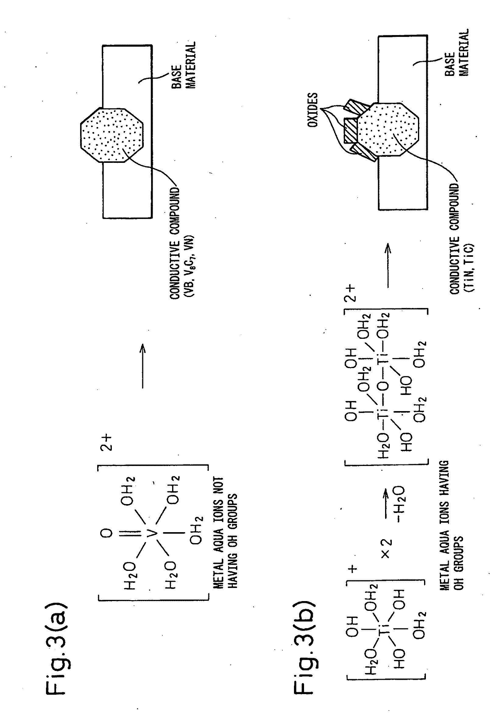
[0307]High corrosion resistance stainless steel and titanium of a length of 50 mm, a width of 50 mm, and a thickness of 0.2 mm were used as base materials of the test materials. As conductive substance particles comprised of metal elements having at most one OH group bonded by metal aqua ions, ones comprised of VB, V8C7, VN, and their mixtures with average particle sizes of 5 μm to 50 μm coated on tungsten carbide superhard core particles with average particle sizes of 100 μm to 300 μm with a binder comprised of Cu mixed with the conductive substance in an amount of 1 wt % were driven into said test base material by a firing pressure of 0.3 MPa to 0.5 MPa to obtain test materials. Further, for comparison, TiN and TiC were driven into said test base materials as conductive substance particles having as ingredients metal elements having OH groups in the metal aqua ions by the blast method under similar conditions to obtain test materials.

[0308]After said blast treatment, the test mate...


PUM


Abstract

The present invention releases a method of producing a metal separator for a solid polymer fuel cell by stainless steel, titanium, or titanium alloy during which securing lower cost and mass producibility by using a material having a high workability to form a complicated shape by a high productivity, then using an inexpensive blast process to drive a conductive substance into the surface of the metal separator member, that is, provides a stainless steel, titanium, or titanium alloy solid polymer fuel cell separator comprised of stainless steel, titanium, or titanium alloy in the surface of which a low ion release conductive substance is buried, having an arithmetic mean roughness (Ra) of the separator surface of 0.5 to 5.0 μm, having a 10-point mean roughness (Rz) of 3 to 20 μm, having an average spacing of surface relief shapes (Sm) of 300 μm or less, having values of a warp rate and twist rate of a separator of 0.1 or less, and having a contact resistance value with respect to carbon paper of 15 mΩcm2 or less at a surface pressure of 1 MPa.

Description

TECHNICAL FIELD[0001]The present invention relates to a solid polymer fuel cell separator used for automobiles, small sized power generating systems, etc. using electric power as a direct drive source and its method of production, more particularly relates to a method of evaluation of warp and twist of a separator. More particularly, it relates to a solid polymer fuel cell member separator which is treated on its surface by a low ion release conductive substance to enhance the flatness of the separator and lower the electrical contact resistance of its surface.BACKGROUND ART[0002]In recent years, rapid progress is starting to be made in development of fuel cells for electric cars due to the success in development of a solid polymer material. A solid polymer fuel cell differs from a conventional alkali type fuel cell, phosphoric acid fuel cell, molten carbonate fuel cell, solid electrolyte fuel cell, etc. in that it uses a hydrogen ion-selective transmission type organic membrane as ...

Claims


Application Information

Patent Timeline
Patent Type & Authority Applications(United States)
IPC IPC(8): H01M8/10H01M2/16H01M2/00B05D5/12G01B11/14B22F1/18
CPCB22F1/02B22F2998/00C22C29/08H01M8/0206H01M8/021Y02E60/50H01M8/0223H01M2008/1095H01M8/0213B22F3/10Y02P70/50B22F1/18
Inventor KIHIRA, HIROSHIKANEKO, MICHIOYAMAGATA, MITSUHARUTANAKA, KOKIIKEMATSU, YOICHIMATSUZAKI, YOICHIKAWAKAMI, KAZUOTOHISADA, WATARUSUZUKI, SUGURU
Owner SINTOKOGIO LTD
Learn More