

Polarization plate, liquid crystal display device and protective film
a technology of liquid crystal display device and polarizing plate, which is applied in the direction of polarising elements, lighting and heating apparatus, instruments, etc., can solve the problems of insufficient removal of moisture contained in the polarizer, insufficient reliability, and optical distortion, etc., and achieves high mechanical strength, high abrasion resistance and mechanical strength. , the effect of sufficient visibility
- Summary
- Abstract
- Description
- Claims
- Application Information
AI Technical Summary
Benefits of technology
Problems solved by technology
Method used
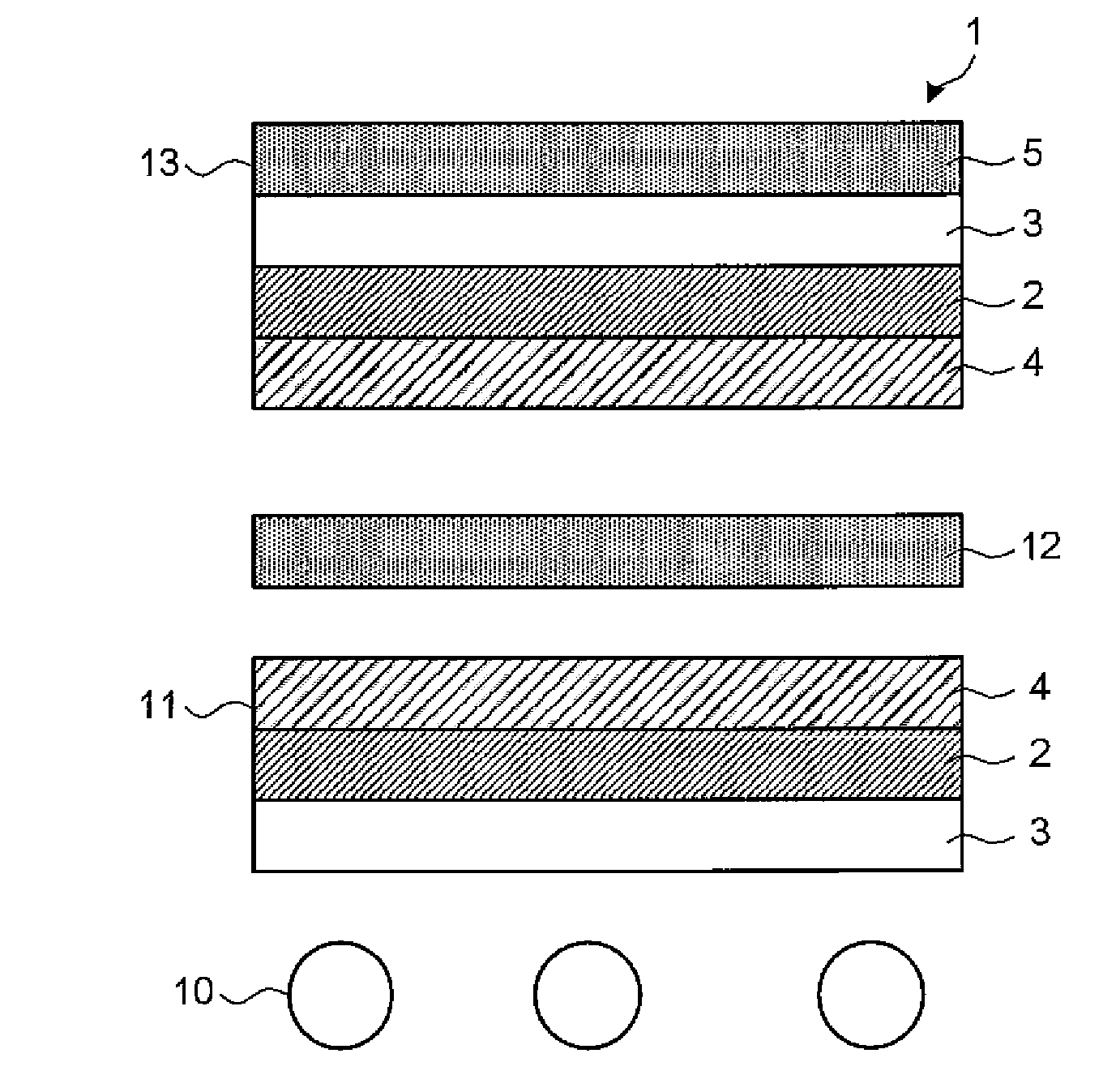
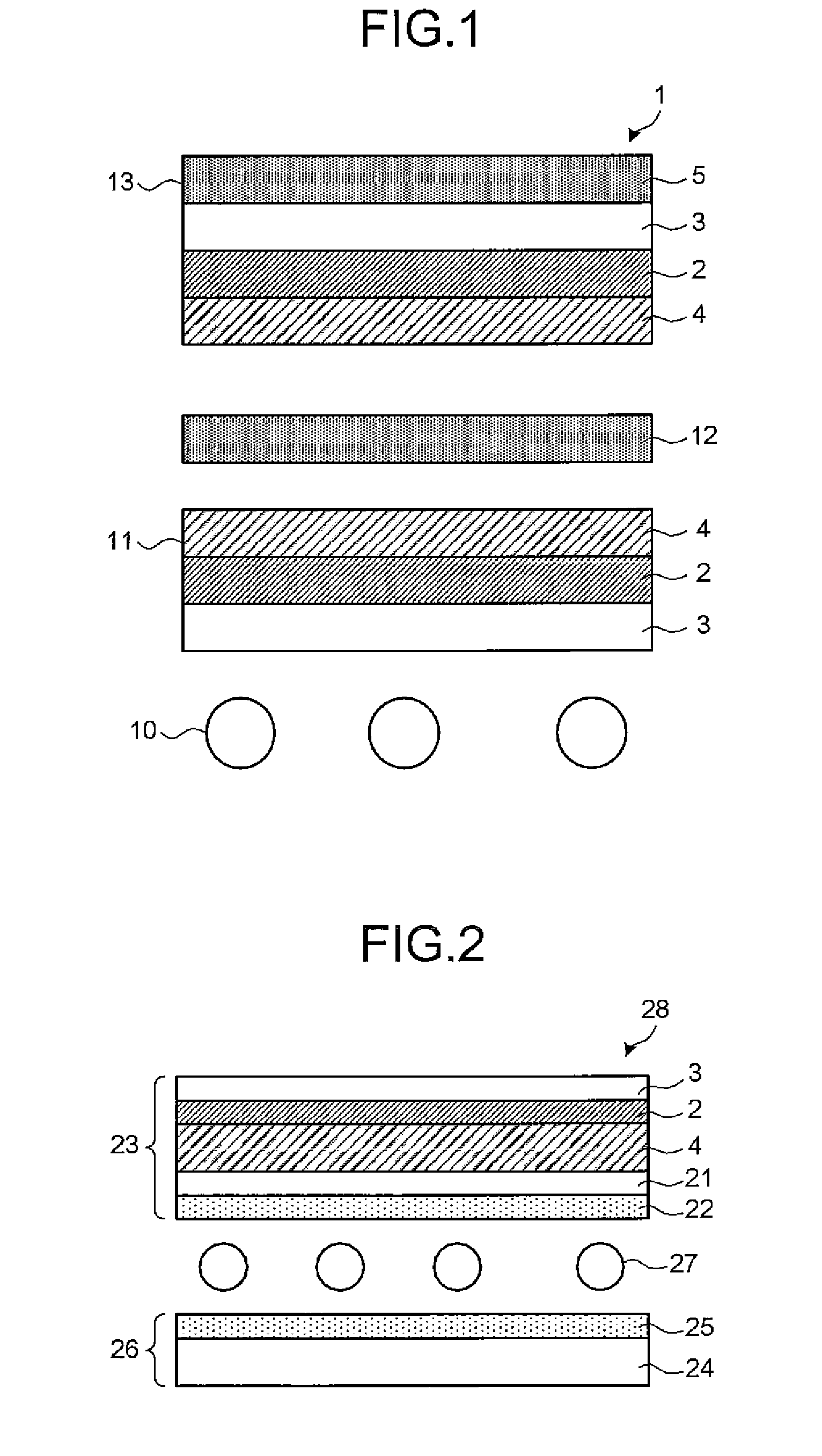
Image

Examples
production example 1
Production of Polarizer
[0209]A polyvinyl alcohol film having a refractive index of 1.545 at a wavelength of 380 nm, a refractive index of 1.521 at a wavelength of 780 nm and having a thickness of 75 μm was uniaxially elongated to 2.5 times, and immersed in an aqueous solution containing 0.2 g / L of iodine and 60 g / L of potassium iodine at 30° C. for 240 seconds, then immersed in an aqueous solution containing 70 g / L of boric acid and 30 g / L of potassium iodine and simultaneously uniaxially elongated to 6.0-times and kept for 5 minutes. Finally, the film was dried at room temperature for 24 hours to yield a polarizer (P) having an average thickness of 30 μm and a polarization degree of 99.95%.
production example 2
Preparation of Material for Forming Hard Coat Layer (H)
[0210]30 Parts of hexafunctional urethane acrylate oligomer, 40 parts of butyl acrylate, 30 parts of isoboronyl methacrylate and 10 parts of 2,2-diphenylethane-1-one were mixed using a homogenizer. A solution of 40% antimony pentaoxide fine particles (average particle diameter: 20 nm; one hydroxyl group is hound to an antimony atom which appears on the surface of a pyrochlore structure) in methyl isobutyl ketone was mixed therewith at a ratio so that the weight of the antimony pentaoxide fine particles occupies 50% by weight of the total solid content of the material for forming the hard coat layer, to prepare the material for forming the hard coat layer (H).
production example 3
Preparation of Material Forming Low Refractive Index Layer (L))
[0211]70 Parts by weight of vinylidene fluoride which is a fluorine-containing monomer and 30 parts by weight of tetrafluoroethylene were dissolved in methyl isobutyl ketone. Subsequently, a hollow silica isopropanol dispersion sol (solid content: 20% by weight, average primary particle diameter: about 35 nm, outer shell thickness: about 8 nm, supplied from Catalyst & Chemicals Industries Co., Ltd.) at 30% by weight in terms of hollow silica solid content relative to the fluorine-containing monomer solid content, dipentaerythritol hexaacrylate (supplied from Shin-Etsu Chemical Co., Ltd.) at 3% by weight relative to the aforementioned solid content, and a photo radical generator Irgacure 184 (supplied from Ciba Specialty Chemicals) at 5% by weight relative to the aforementioned solid content were added thereto, to prepare the material for forming the low refractive index layer (L).
PUM
| Property | Measurement | Unit |
|---|---|---|
| wavelength | aaaaa | aaaaa |
| wavelength | aaaaa | aaaaa |
| thickness | aaaaa | aaaaa |
Abstract
Description
Claims
Application Information