Method and Apparatus for Increasing Blood Flow in a Body Part

a technology of blood flow and body parts, applied in the field of methods and apparatus for increasing blood flow to a body part, can solve the problems of slow tissue healing, amputation of the affected limb, slow healing, etc., and achieve the effects of enhancing microvascular flow, enhancing microvascular flow, and easy application and removal

Inactive Publication Date: 2009-10-29
RGT UNIV OF CALIFORNIA
View PDF47 Cites 39 Cited by
  • Summary
  • Abstract
  • Description
  • Claims
  • Application Information

AI Technical Summary

Benefits of technology

[0010]It is an advantage of the present invention to provide a device and method for applying uniform compression to a body part for enhancing microvascular flow in skin, muscle and bone without contacting the area under treatment.
[0011]Another advantage of the present invention is to provide a device for enhancing microvascular flow in a body part that is easily applied and removed to permit access for inspection of the body part.
[0012]Still another advantage of the present invention is to provide a device and method for increasing popliteal artery inflow to the body part.
[0013]According to the present invention, blood flow to the target body part, e.g., a leg, arm or a portion of the torso, is increased by applying external air pressure around the body part, without physically contacting the affected area with any part of the device.
[0014]In an exemplary embodiment, the inventive device comprises a substantially air-tight enclosure that is dimensioned to enclose the affected area of the body part while extending slightly beyond the affected area to avoid direct contact with the affected area; one or more releasable seals for sealing the enclosure around the body part; a pump in fluid communication with the enclosure for introducing pressurized air into the enclosure; and a pressure gauge for monitoring pressure within the enclosure. A filter device is preferably inserted into a line between the pump and the enclosure to prevent introduction of potentially harmful contaminants (biological or chemical) into the affected area. An air heater / cooler may be incorporated in the pump or placed in-line with the pump to permit control of the air temperature within the enclosure. A computer controller may be provided to receive feedback from the pressure gauge and provide commands to the pump, or to a valve for controlling air flow from the pump, to maintain a selected pressure within the enclosure. In an alternate embodiment, the enclosure may have an openable access port that is substantially air-tight when closed to facilitate access for examination of the affected area without removal of the device.
[0015]In another embodiment, the device is configured for alternating pressure and vacuum. In the case of a fully flexible enclosure, i.e., a bag, an internal frame is disposed within the bag to prevent contact between the inner walls of the bag and the affected area when the bag is evacuated. The internal frame may be formed from stainless steel, titanium, plastic, or other polymer that is sufficiently rigid to support the bag and is capable of being safely sterilized to avoid contamination of the affected area.

Problems solved by technology

Inadequate blood flow into and out of the injured limb can lead to such problems as pain upon exertion of the limb, slow healing of injuries, breakdown of soft and hard tissues leading to slow healing of tissues or even gangrene, which can lead to amputation of the affected limb.
Moreover, diabetes is also the main cause of non-traumatic lower extremity amputations in orthopedics.
Use of vasodilator drugs does not aid in the healing of diabetic foot ulcers.
Hyperbaric oxygen is occasionally effective, however raising the oxygen content of the blood is of less value when the blood supply to the foot is severely impaired.
Existing devices exhibit a number of disadvantages, including that they all directly contact the body part in some manner to apply compression (via an inflatable air bladder or elastic compression garment).
By touching the skin, existing devices can be problematic for post-surgical patients or other patients in whom direct cutaneous compression may cause pain, compression of delicate surgical repairs, or contamination of the wound site.
Further, they will not work on patients with casts or external fixators since they operate by physically applying pressure against the skin, or against a sterile fabric directly covering the skin.
This makes wound inspection difficult, since the bandage must be removed and replaced every time a wound check is performed.
Tests have shown that prior art compression devices that physically contact the surface do not uniformly compress the body part.
Since intermittent pneumatic compression devices operate in much the same manner as the pneumatic tourniquets, it is expected that they similarly would not provide uniform compression.

Method used


Image

  • Method and Apparatus for Increasing Blood Flow in a Body Part
  • Method and Apparatus for Increasing Blood Flow in a Body Part
  • Method and Apparatus for Increasing Blood Flow in a Body Part

Examples


example 1

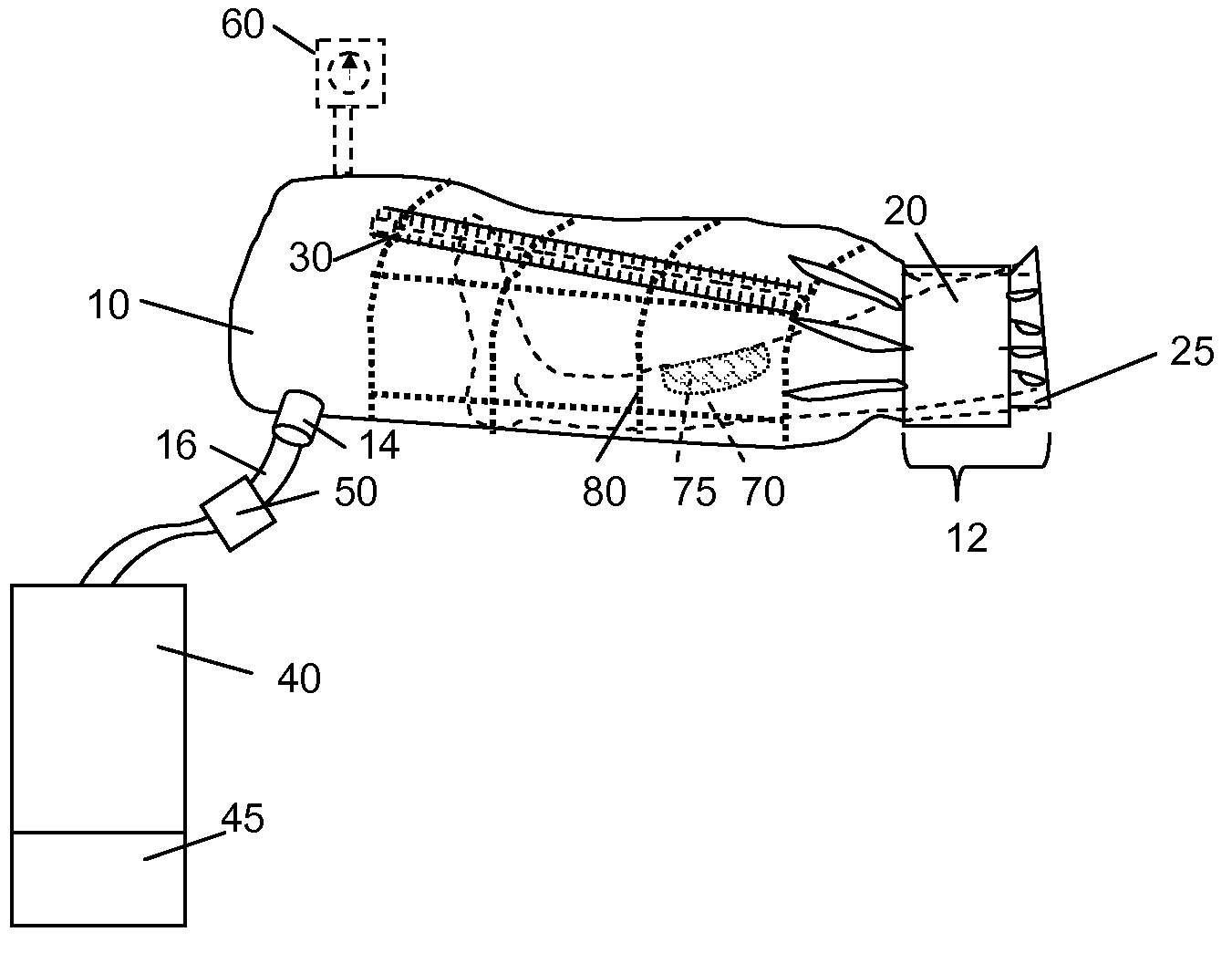
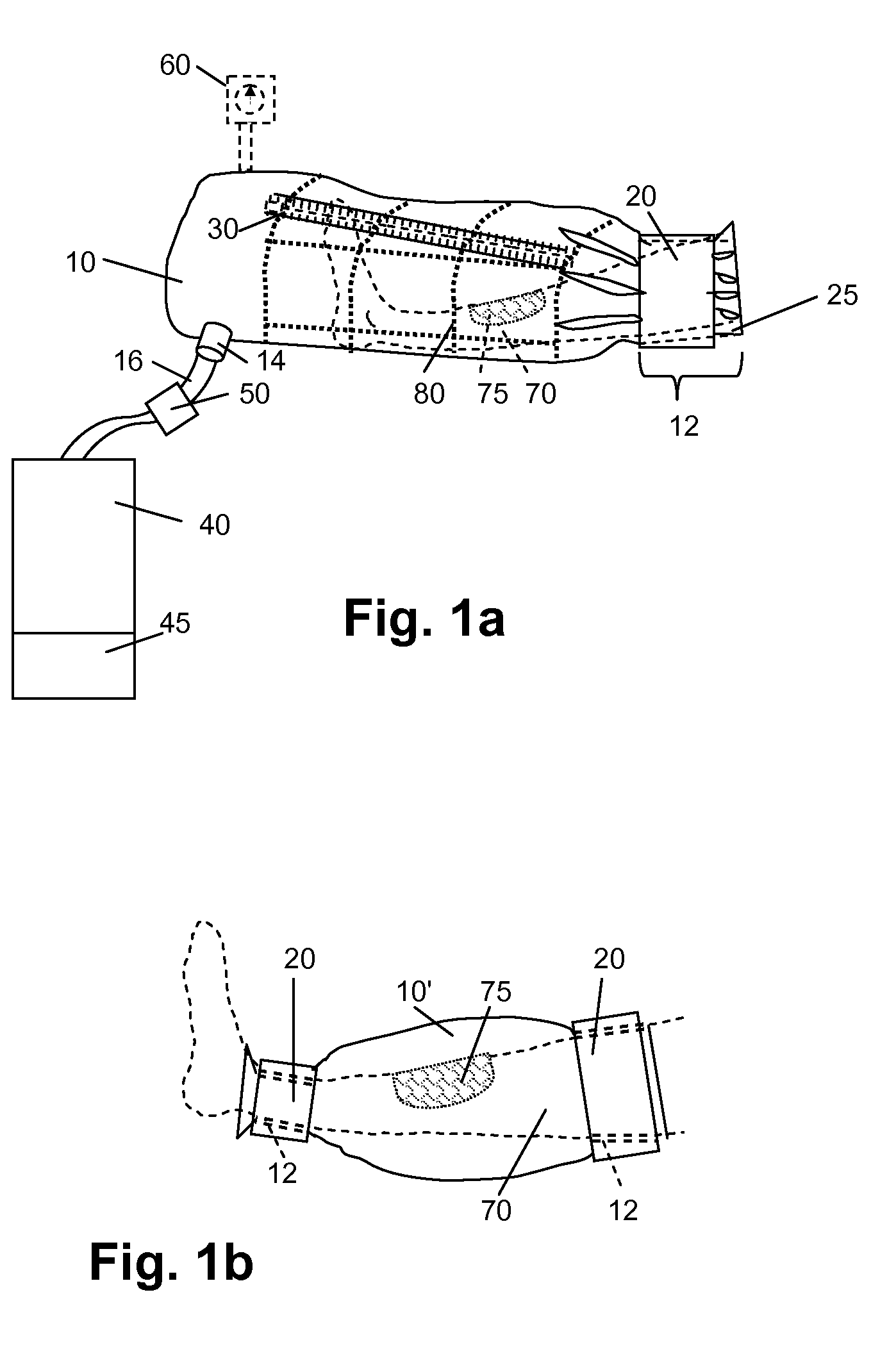
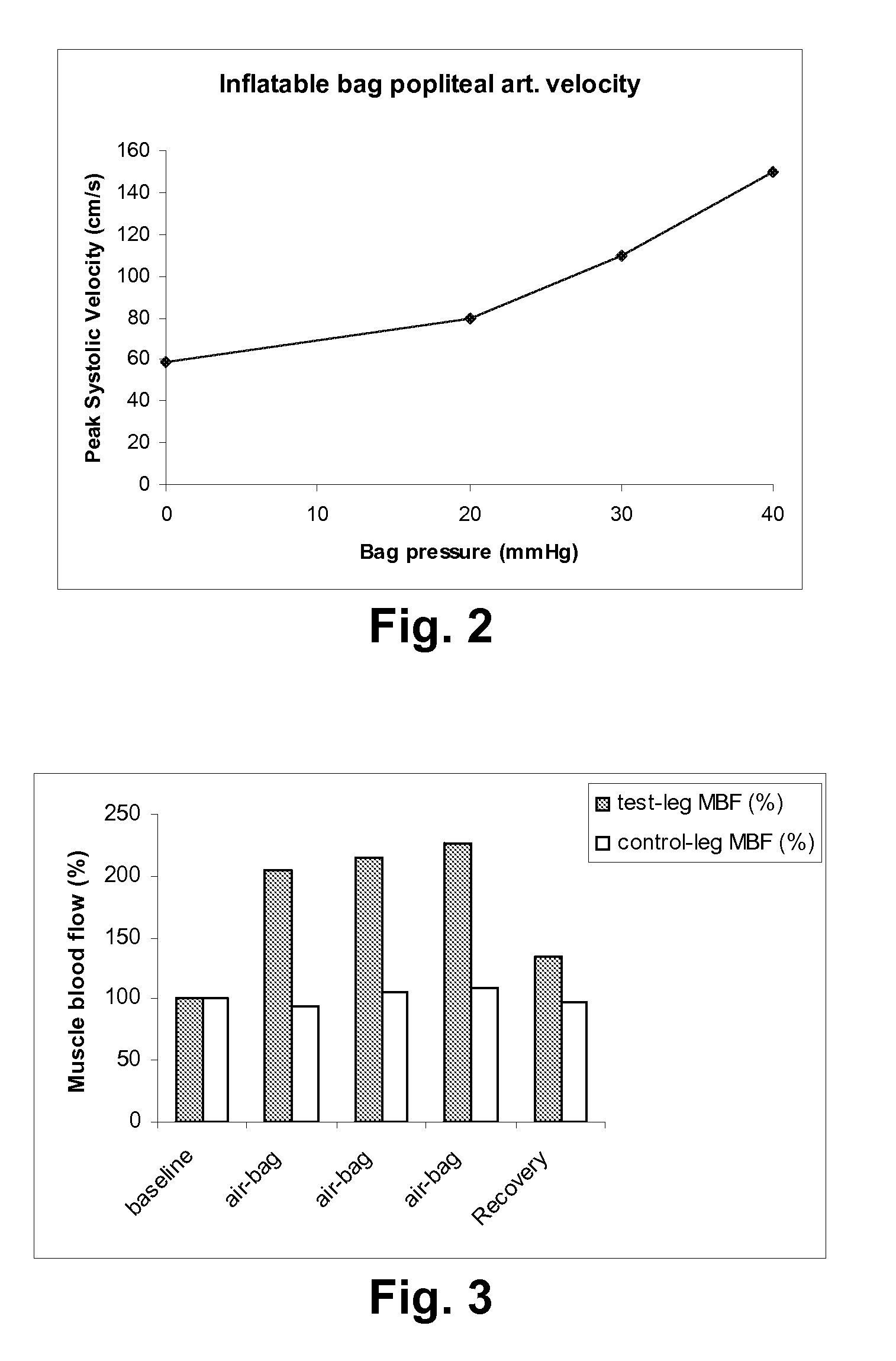
[0043]The leg of a volunteer was inserted into a bag, sealed using a conventional blood pressure cuff, and pressurized to 40 mmHg. The bag was formed from HDPE sheeting, sealed to be substantially airtight. (A Neoprene®sleeve covered by plastic sheeting was also tried and was found easier to apply.) Air tubing was connected between a port formed in the bag and an air pump. The bag was not in contact with the skin. Baseline blood flows were measured using photoplethysmography and Doppler ultrasound. Once the desired pressure level was attained, periodic measurements were taken after which pressurization was terminated and the bag allowed to deflate.

[0044]The device was found to increase the large artery inflow to the leg—the popliteal artery peak systolic velocity is increased by about 140%, compared to about 20-25% with existing devices. Pressure treatment increased microvascular skin blood flow in the leg; increased microvascular muscle blood flow in the leg; and modulated extremit...


PUM


Abstract

An enclosure is dimensioned to enclose an affected area of a body part plus a small margin around which a releasable seal is attached to make the enclosure substantially airtight around the body part without contacting the area to be treated. A port in the enclosure is attached to tubing for connection of a pump for forcing air under pressure into the enclosure. In the preferred embodiment, the enclosure is an inflatable plastic bag. The compression provided by the air pressure is applied uniformly to the body part to increase blood flow within the body part without physically contacting the affected area of the body part. In one embodiment, the pump is a combination air and vacuum pump so that pressures within the enclosure may be cycled between high and low pressures.

Description

RELATED APPLICATIONS[0001]This application claims priority of U.S. Provisional Application No. 60 / 802,215, filed May 19, 2006, which is incorporated herein by reference in its entirety.FIELD OF THE INVENTION[0002]The present invention relates to a method and apparatus for increasing blood flow to a body part, and more specifically to a method and apparatus that uses air pressure rather than physical contact with the area that is being treated.BACKGROUND OF THE INVENTION[0003]Patients suffering from an injury or illness that impairs blood circulation in a limb or other body part require enhancement of the circulation in order to heal, or in extreme cases, to save the limb and provide for full recovery. Inadequate blood flow into and out of the injured limb can lead to such problems as pain upon exertion of the limb, slow healing of injuries, breakdown of soft and hard tissues leading to slow healing of tissues or even gangrene, which can lead to amputation of the affected limb.[0004]...

Claims


Application Information

Patent Timeline
Patent Type & Authority Applications(United States)
IPC IPC(8): A61B17/00A61F2/958
CPCA61H23/04A61H9/005
Inventor HARGENS, ALAN R.MACIAS, BRANDON R.NEUSCHWANDER, TIMOTHY B.ZHANG, QIUXIA
Owner RGT UNIV OF CALIFORNIA
Why Eureka
Try Eureka