Plastic optical fiber cable and method of signal transmission using the same

a technology of optical fiber cable and plastic fiber, applied in the direction of optical fiber with multi-layer core/cladding, optical waveguide light guide, instruments, etc., can solve the problems of increasing transmission loss, poor workability, and high cost of quartz optical fiber, etc., to achieve superior long-term heat resistance and increase transmission loss

Active Publication Date: 2009-11-12
MITSUBISHI CHEM CORP
View PDF4 Cites 14 Cited by
  • Summary
  • Abstract
  • Description
  • Claims
  • Application Information

AI Technical Summary

Benefits of technology

[0025]An object of the present invention is to provide a plastic optical fiber cable with which no significant increase in transmission loss occurs in a high temperature environment, the cable being superior in long-term heat resistance, and a method of signal transmission achieved by using this.
[0052]According to the present invention, it is possible to provide a plastic optical fiber cable with which no significant increase in transmission loss occurs in a high temperature environment, the cable being superior in long-term heat resistance, and a signal transmission system using the same.

Problems solved by technology

Such quartz optical fibers, however, are expensive and poor in workability.
However, POF cables having a coating layer made of a polyamide resin (nylon-based resin) material can suffer from problems as follows.
However, the polymerization of a polyamide resin is accompanied by the establishment of a chemical equilibrium, so that the resultant polymer is always contaminated with a monomer or oligomer derived from a feed material for the polyamide resin.
In addition, it has been found that particularly significant increase in transmission loss is observed when the outermost cladding layer is made of a fluorine-containing olefin resin having a tetrafluoroethylene (TFE) unit and when heat of crystal fusion is greater than a certain amount of value.
This often causes reduction in transparency of the cladding material, which can result in significant deterioration of transmission characteristics of the POF cable.
As a result, more structural mismatch would happen at the core-cladding interface or a cladding-cladding interface if there are two or more cladding layers with a tendency of significant deterioration of transmission characteristics of the POF cable.
In particular, the POF cables that are intended to be used in an automobile are required not to cause any significant increase in transmission loss for a long period of time of longer than 5,000 hours, in an environment at 105° C. However, it is difficult for the conventional POF cables as described in the aforementioned Patent Documents to meet the required performance because increase in transmission losses is inevitable for the aforementioned reasons, after having been placed in a high temperature environment for a long period of time.
In addition, it has been reported that optical properties of a POF may be significantly degraded due to excessive stress on the POF when the POF is coated with a nylon-based resin such as nylon 66 having a relatively high melting point.
The document discloses that, in the POF cable, the polyamide 66 resin having a high melting point is directly coated over the bare POF at a high coating temperature, which brings about deformation of the POF and increase in transmission loss, and hence nylon-based resins having a high melting point are not suitable as a coating material for POFs.
Considering now light emitting diodes (LEDs) which have been used as a light source for POFs, those with a center emission wavelength of around 650 nm are most commonly used but currently cannot provide sufficient long-term heat resistance at 100° C. or higher.
The reason is that such LEDs are made of a GaAlAs-based material and their aluminum component, if contained too much, tends to lower the LED's own heat resistance.
In addition, POFs which are placed in such a high temperature environment typically undergo increase in electronic transition absorption due to thermal oxidative deterioration of a bare POF and increase in Rayleigh scattering due to migration of a low-molecular-weight compound contained in a coating material into the bare POF.
As apparent from the above, the transmission losses in the POFs described in these Patent Documents are too high to use them in practice for in-vehicle LAN communication wiring.
However, the transmission loss in a POF is likely to increase in such short-wavelength regions when the POF is placed in a high temperature environment at 100° C. or higher because it tends to be affected by the aforementioned increase in electronic transition absorption or Rayleigh scattering.
It has therefore been believed to be difficult to practically use a signal transmission system including a POF and an LED having a center emission wavelength in a range of 500 nm to 600 nm, in a high temperature environment such as in an automobile.

Method used


Image

  • Plastic optical fiber cable and method of signal transmission using the same
  • Plastic optical fiber cable and method of signal transmission using the same
  • Plastic optical fiber cable and method of signal transmission using the same

Examples


reference example 1

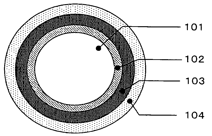
[0268]PMMA (refractive index of 1.492) was used for a core material, a copolymer (refractive index of 1.416 to 1.417) made of 3FM / 17FM / MMA / MAA (composition ratio of 51 / 31 / 17 / 1 (% by mass)) was used for a first cladding material, and a copolymer made of VdF / TFE / HFP (composition ratio of 43 / 48 / 9 (% by mass), refractive index of 1.375, heat of crystal fusion (ΔH) of 14 mJ / mg) was used for a second cladding material (“MAA” refers to a methacrylic acid). These polymers were molten and fed to a spinning head at 220° C. A concentric dual injection nozzle was used for bicomponent spinning, and the polymers were stretched to double in the fiber axis direction in a hot-air furnace at 140° C. to obtain a bare POF having a diameter of 1 mm in which each cladding layer has a thickness of 10 μm.

[0269]The transmission loss of the resultant bare POF was as good as 134 dB / km, and the transmission loss after a heat resistance test was also as good as 175 dB / km.

[0270]Around the resultant bare POF, a P...

example 1

[0274]A functional coating layer was formed around the POF primary cable having an outer diameter of 1.5 mm, which was prepared in Reference Example 1. Used as the feed material for the functional coating layer was a nylon 6 resin composition (bromine atom content of 6.8% by mass) that contains 83.5% by mass of nylon 6 resin (available from UBE INDUSTRIES, LTD., trade name: UBE nylon 1011 FB), 10% by mass of brominated polystyrene (available from ALBEMARLE CORPORATION, trade name: HP-3010, molecular weight of 50,000 given in terms of the equivalent polystyrene molecular weight as measured using GPC), 5% by mass of antimony pentoxide (available from NISSAN CHEMICAL INDUSTRIES, LTD., trade name: San-Epok), and 1.5% by mass of ultramarine blue. This resin composition was coated by using a crosshead cable coating machine having a crosshead die at 240° C. to obtain a POF secondary cable of an outer diameter of 2.3 mm, which has a functional coating layer (thickness of 400 μm). The conten...

example 2

[0277]A functional coating layer was formed around the POF primary cable having an outer diameter of 1.5 mm, which was prepared in Reference Example 1. Used as the feed material for the functional coating layer was a nylon 6 resin composition that contains 85% by mass of nylon 6 resin (available from UBE INDUSTRIES, LTD., trade name: UBE nylon 1011 FB), 15% by mass of melamine cyanurate (available from NISSAN CHEMICAL INDUSTRIES, LTD., trade name: MC-4000), and 1.5% by mass of ultramarine blue. This resin composition was coated by using a crosshead cable coating machine having a crosshead die at 240° C. to obtain a POF secondary cable of an outer diameter of 2.3 mm, which has a functional coating layer (thickness of 400 μm).

[0278]The resultant POF secondary cable was evaluated and the results are given in Table 2 below. The resultant POF secondary cable had an initial transmission loss of 135 dB / km and a transmission loss after a heat resistance test was 198 dB / km. The heat resistan...


PUM


Abstract

A plastic optical fiber cable includes: a bare optical fiber including a core made of a poly(methyl methacrylate) or a copolymer including methyl methacrylate as a major component and a cladding layer including, at least in the outermost layer, a layer made of a certain fluorine-containing olefin-based resin; and a coating layer provided on the outer surface thereof. The coating layer includes a protective coating layer, a light blocking coating layer, and a functional coating layer, the layers being provided in the order mentioned from inner side. The protective coating layer is made of a certain resin material. The light blocking coating layer is made of a nylon-based resin including, as a major component, nylon 11 or nylon 12, the nylon-based resin containing monomer and oligomer compounds derived from the nylon-based resin in an amount of a certain range. The functional coating layer is made of a nylon-based resin composition having a crystalline melting point within a certain range, the nylon-based resin composition containing a certain amount of melamine cyanurate or bromine atoms and further containing a certain amount of inorganic chromatic pigments, or the layer is made of a nylon-based resin composition having a crystalline melting point of within a certain range and an oxygen transmission rate within a certain range.

Description

TECHNICAL FIELD[0001]The present invention relates to a plastic optical fiber cable having a coating layer made of a nylon-based resin and, more particularly, to a plastic optical fiber cable having excellent long-term heat resistance in a high temperature environment at around 100 to 110° C., and a method of signal transmission achieved by using a combination of this optical fiber cable and a visible light emitting diode having a center emission wavelength in a range of 500 nm to 600 nm.BACKGROUND ART[0002]Conventional optical fibers made of quartz, which is capable of providing good optical transmission across a broad wavelength spectrum, have been in practical use mainly for trunk lines. Such quartz optical fibers, however, are expensive and poor in workability. Accordingly, plastic optical fibers (hereinafter, abbreviated as “POF”), which offer advantages such as being much more inexpensive and lightweight, having larger apertures and easily workable end surfaces, and being easi...

Claims


Application Information

Patent Timeline
Patent Type & Authority Applications(United States)
IPC IPC(8): G02B6/44
CPCG02B6/02033G02B1/045G02B6/00G02B6/44
Inventor AOYAGI, AMANETSUKAMOTO, YOSHIHIROFUJISHIGE, YASUSHIMAEDA, YOSHIKOKIMURA, TSUYOSHI
Owner MITSUBISHI CHEM CORP
Why Eureka
Try Eureka