
Protective coating with high adhesion and articles made therewith

a protective coating and high adhesion technology, applied in the direction of instruments, machines/engines, light beam reproducing, etc., can solve the problems of affecting the adhesion of substrates, and affecting the performance of coatings, etc., and achieves the effect of reducing the strain tolerance and adhesion of substrates

Active Publication Date: 2009-11-12
GENERAL ELECTRIC CO
View PDF13 Cites 39 Cited by
  • Summary
  • Abstract
  • Description
  • Claims
  • Application Information

AI Technical Summary

Problems solved by technology

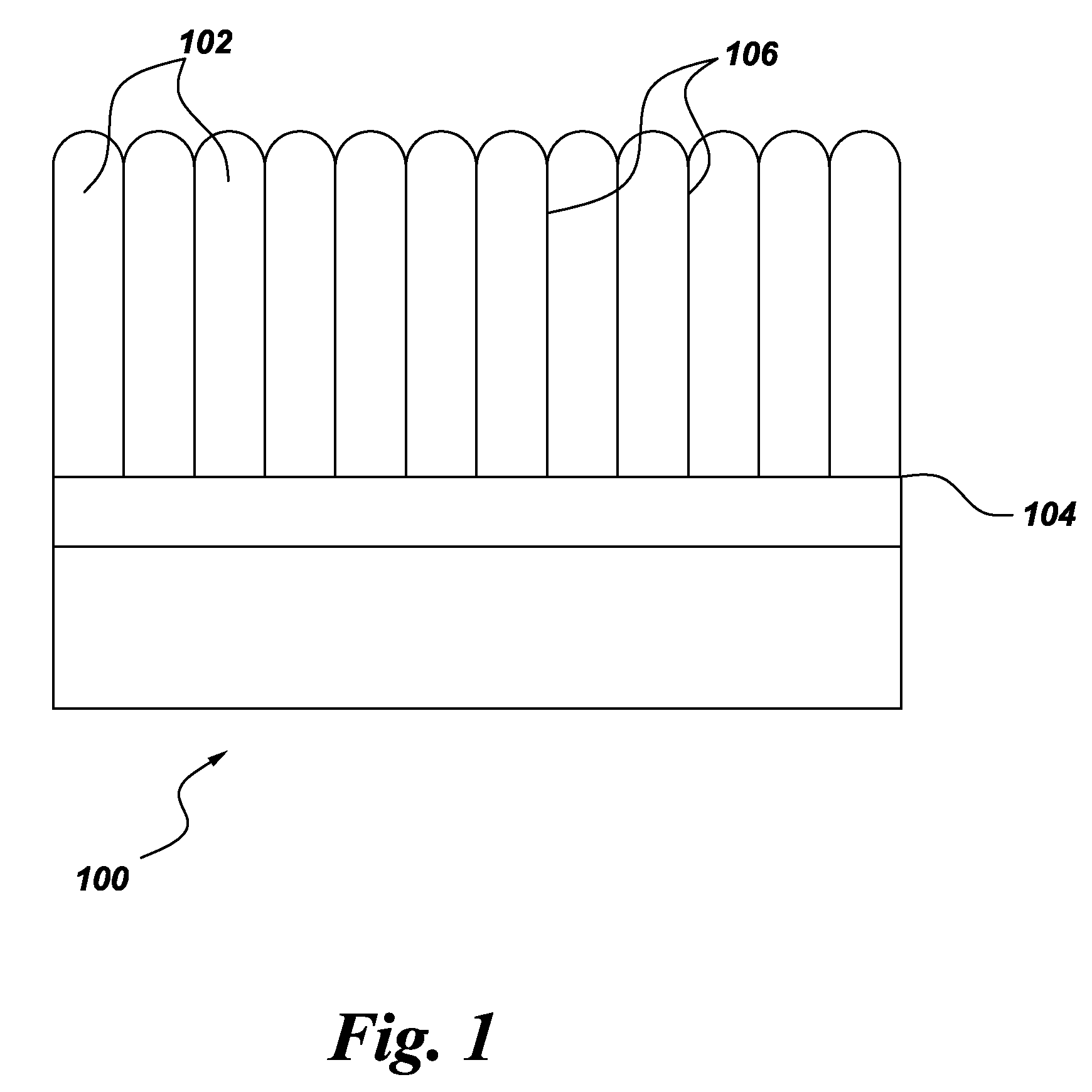
Although PVD processes provide coatings with very attractive strain tolerance properties, they tend to be relatively expensive and applicable to relatively small components when compared with plasma spray processes, because PVD processes require a vacuum chamber and supporting equipment.
On the other hand, traditional thermal spray processes tend to produce coatings with lower strain tolerance and substrate adhesion than PVD processes, and generally require ancillary surface preparation processes, such as grit blasting and deposition of rough bond coats, to provide adequate adhesion to the underlying component.

Method used


Image

  • Protective coating with high adhesion and articles made therewith
  • Protective coating with high adhesion and articles made therewith
  • Protective coating with high adhesion and articles made therewith

Examples


example 1

[0028]An yttria-stabilized-zirconia (YSZ) coating was produced on an Alloy 718 plate using a DC plasma gun. The feedstock material was 8 wt % YSZ powder with a median particle diameter (d50) of 0.4 micrometers suspended in ethanol at 10 percent by weight, using polyethyleneimine as a dispersant (at 0.2 percent by weight of the solids). The suspension was injected at a feed rate of about 0.25 pounds (about 113 grams) of YSZ per hour into a Northwest Mettech Axial III torch through the center tube of a tube-in-tube atomizing injector with a nitrogen atomizing gas flowing through the outer tube. The total torch power was about 120 kW, with a current of about 200 amperes maintained for each of the three torch electrodes, and a total gas flow of 245 liters per minute that consisted of a mixture of 30% argon, 55% nitrogen, and 15% hydrogen. The plasma torch was rastered across the substrate at 600 millimeters (mm) per second while maintaining a constant spray distance of 76 mm distance be...

example 2

[0031]YSZ coatings were produced on substrates of Rene N5 with a platinum nickel aluminide diffusion bondcoat. The bondcoat surface was prepared by grit blasting with 80 grit size aluminum oxide at 40 psi pressure. The average Ra roughness of the substrate surface was about 50 microinches. Coatings were sprayed with the same coating parameters as for Example 1. The coatings were about 228 micrometers thick. The tensile adhesion strength was measured using the ASTM C633 specification. The average adhesion strength was 55.6+ / −11.6 MPa.

example 3

[0032]A YSZ coating was produced on a 304 stainless steel plate grit blasted with 60 grit aluminum oxide at 50 psi pressure. The coating was produced using the same parameters as described in Example 1, except that the torch to substrate spray distance was 50 mm instead of 76 mm (which was used for examples 1 and 2).

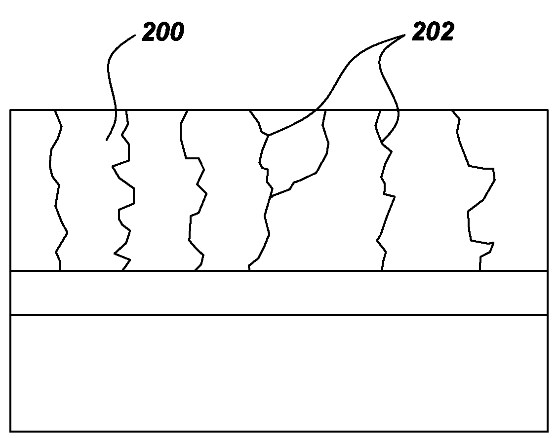
[0033]The resultant coating comprised the structure illustrated in FIG. 2, with a matrix comprising a randomly oriented, substantially equiaxed grain morphology; and a plurality of vertically oriented cracks disposed in the matrix. The intracrack density and vertical crack density were measured from cross-sectional images of polished surfaces. The area fraction of solid phases was determined at a magnification of 400× from the contrast in light microscopy to be about 99%. The linear density of vertical cracks that extended at least 50% through the thickness was 560 cracks per inch and the density that extended at least 75% through the thickness was 340 cracks per inch.

[0...


PUM

PropertyMeasurementUnit
widthaaaaaaaaaa
aspect ratioaaaaaaaaaa
widthaaaaaaaaaa

Abstract

Coatings and articles suitable for use in high temperature environments, for example, are presented. One embodiment is a coating that comprises a plurality of elongate material growth domains defined between domain boundaries. The domains have an intra-domain density of at least about 75% of theoretical density, have a substantially equiaxed grain morphology, and comprise a plurality of at least partially melted and solidified particles. Another embodiment is a coating that comprises a matrix comprising a substantially equiaxed grain morphology and a plurality of vertically oriented cracks disposed in the matrix. Further embodiments include articles comprising one or more of the coatings described above.

Description

BACKGROUND[0001]This invention relates to coatings for high temperature applications, such as gas turbine assemblies.[0002]The design of modern gas turbines is driven by the demand for higher turbine efficiency. It is widely recognized that turbine efficiency can be increased by operating the turbine at higher temperatures. In order to assure a satisfactory life span at these higher temperatures, thermal barrier coatings (hereinafter referred to as “TBCs”) are applied to airfoils and combustion components of the turbine, such as transition pieces and combustion liners, using various techniques.[0003]One important aspect of TBC's is their ability to tolerate strain in the underlying component without becoming detached from the component. Because TBC's are typically made of ceramic materials having much lower inherent ductility than their underlying metallic components, various microstructural features are typically incorporated into the TBC to provide it with improved strain toleranc...

Claims


Application Information

Patent Timeline
Patent Type & Authority Applications(United States)
IPC IPC(8): B32B3/00
CPCC23C30/00Y02T50/67F01D25/005C23C4/105Y10T428/24893Y10T428/31Y10T428/24802Y10T428/24926Y10T428/24471Y10T428/24479Y10T428/26C23C4/11Y10T428/249986Y02T50/60
Inventor ROSENZWEIG, LARRY STEVENRUUD, JAMES ANTHONYLEBLANC, LUC STEPHANETHOMAS, PAUL MATTHEWSMITH, SCOTT SHERIDAN
Owner GENERAL ELECTRIC CO
Learn More