Process For Manufacturing Free Standing Thermoplastic Polymeric Films

a manufacturing process and thermoplastic technology, applied in the field of polymer films, can solve the problems of damage to equipment, poor thickness variability of the resulting film, and distinct drawbacks of manufacturing techniques with respect to thin freestanding polymeric films, etc., to achieve uniform thickness, reduce thickness, and improve production efficiency

Inactive Publication Date: 2009-11-26
TRIPARTISAN TECH
View PDF13 Cites 50 Cited by
  • Summary
  • Abstract
  • Description
  • Claims
  • Application Information

AI Technical Summary

Benefits of technology

[0025]The present invention discloses a significantly modified cast film process that offers particular advantages not previously known in the art with known prior art processes. Thin polymer films having a thickness of less than 10 μm may be manufactured under conditions that allow substantially uniform thickness and especially films that are biaxially oriented to reduce thickness. The presence of the assist layer in the novel process allows for much higher drawdown ratios than would otherwise be possible, and therefore much thinner films. This drawdown is accomplished by having the cooling apparatus running at a higher velocity than the polymer coming out of the die.
[0026]In the novel process, the multilayer melt curtain is stretched while still in the molten state, significantly reducing its thickness, since it is coextruded with a sufficient supporting assist layer that functions as a mechanical support layer to keep the film layer from breaking during the drawdown phase of the process. This overcomes curtain break problems experienced in the prior art processes.
[0027]Since each layer is separately shaped into a film, and then the various films may be brought into contact at the last second, the individual polymer layers can be different temperatures and viscosities. This novel process enables very thin freestanding films made from amorphous pol

Problems solved by technology

Although films can be coated onto other substrates which are nanometers in thickness, these are not freestanding films, since they cannot be peeled off the substrate and handled in a robust way.
Each genre of manufacturing techniques has distinct drawbacks and disadvantages with respect to thin freestanding polymeric films.
The disadvantage of this technique is that it is primarily limited to a narrow range of olefinic polymers such as polyethylene, and the thickness variability of the resulting film is often poor.
This high pressure can damage the equipment and limit the productivity of the extrusion operation.
The blown film process is also limited in the degree of filler such as amorphous silica or carbon black which can be used.
The presence of filler usually dramatically increases the viscosity (and therefore the pressure drop) of the melt.
This filler also reduces the melt strength, resulting in instability of the vertical column of polymer and causing repeated breaks.
This would limit the minimum thickness of the films made with such a process, as well as the productivity and economics derived.
Chemically cross linked polymers cannot be used for the same reason that high fillers cannot be incorporated, in particular, they would cause an exceedingly high pressure drop.
In addition to equipment limitations, the high pressure drop which would result causes a phenomenon called “melt fracture” through the die.
Melt fracture results in very poor extruded quality.
The disadvantage of the cast film process is that, like blown film, the thickness and speed of the extruded materials made using this technique depends on the melt strength of the thermoplastic which is being extruded.
There are many valuable thermoplastics such as polycarbonate, polymethyl methacrylate, and other amorphous polymers which do not have good melt strength.
Thus, the cast film process works adequately when trying

Method used


Image

  • Process For Manufacturing Free Standing Thermoplastic Polymeric Films
  • Process For Manufacturing Free Standing Thermoplastic Polymeric Films
  • Process For Manufacturing Free Standing Thermoplastic Polymeric Films

Examples


example 1

[0174]A thin polycarbonate film was manufactured. The film is useful as a capacitor dielectric.

[0175]Polycarbonate pellets purchased from Mitsubishi were dried at 121 degrees Celsius for 12 hours. The polycarbonate pellets were fed into a 25 mm single screw extruder, with a melt temperature of 243 degrees Celsius. The screw on the extruder was a standard single screw with a Maddox mixer, and the screw speed was adjusted so as to obtain a rate of 22 g / min.

[0176]The assist layer was prepared using Na214 low density polyethylene (LDPE) purchased from Equistar corp. The LDPE was undried, and was fed into another 25 mm single screw extruder which was operated at melt temperature of 216 degrees Celsius. The screw on the extruder was a standard single screw with a Maddox mixer, and the screw speed was adjusted so as to get a rate of 45 g / min.

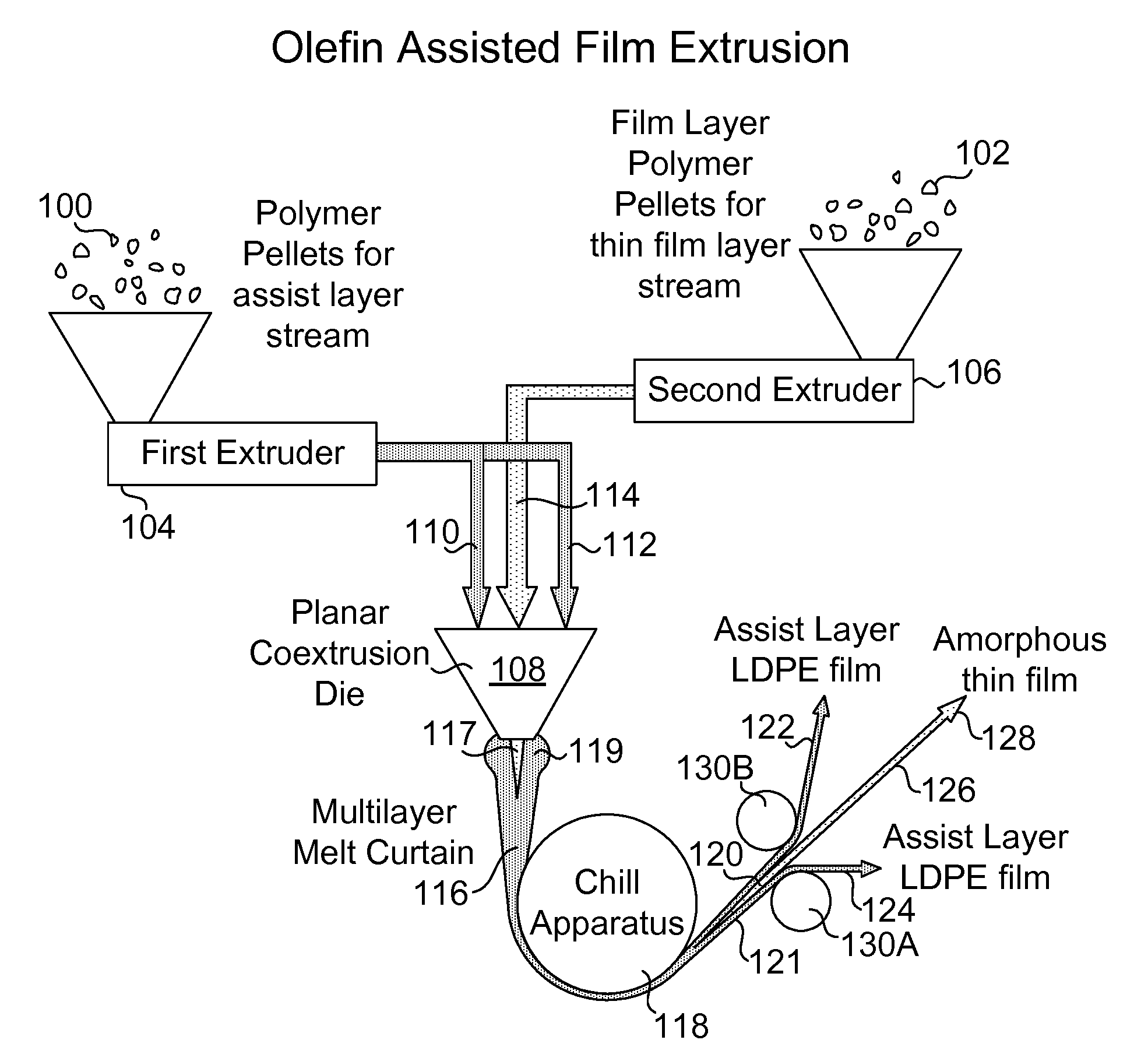
[0177]The two polymers were brought together in a standard coextrusion feedblock in an ABA structure, where A is the assist layer (low density polyeth...

example 2

[0180]Polycarbonate pellets purchased from Mitsubishi were dried at 121 degrees Celsius for 12 hours. The polycarbonate pellets were fed into a 25 mm single screw extruder, with a melt temperature of 243 degrees Celsius. The screw on the extruder was a standard single screw with a Maddox mixer, and the screw speed was adjusted so as to obtain a rate of 22 g / min.

[0181]The assist layer was prepared using Na214 low density polyethylene (LDPE) purchased from Equistar corp. The LDPE was undried, and was fed into another 25 mm single screw extruder which was operated at melt temperature of 216 degrees Celsius. The screw on the extruder was a standard single screw with a Maddox mixer, and the screw speed was adjusted so as to get a rate of 45 g / min.

[0182]The two polymers were brought together in a standard coextrusion feedblock in an ABA structure, where A is the assist layer (low density polyethylene) and B is the molten polycarbonate. Thus, the molten polycarbonate was in the center, and...

example 3

[0185]A thin acrylic film was made. The PMMA film is useful to enhance gloss of an injection molded device.

[0186]V044 polymethyl methacrylate (PMMA) purchased from Arkema Inc. was dried for 12 hours at 79 degrees Celsius. The PMMA pellets were fed into a 25 mm single screw extruder, with a melt temperature of 235 degrees Celsius. The screw on the extruder was a standard single screw with a Maddox mixer, and the screw speed was adjusted so as to obtain a rate of 23 g / min.

[0187]The assist layer was prepared using Na214 LDPE purchased from Equistar Corp. The LDPE was undried, and was fed into another 25 mm single screw extruder which was operated at melt temperature of 218 degrees Celsius. The screw on the extruder was a standard single screw with a Maddox mixer, and the screw speed was adjusted so as to get a rate of 45 g / min.

[0188]The two polymers were brought together in a standard coextrusion feedblock in an ABA structure, where A is the assist layer (LDPE) and B is the molten PMMA...


PUM

PropertyMeasurementUnit
Fractionaaaaaaaaaa
Thicknessaaaaaaaaaa
Lengthaaaaaaaaaa

Abstract

This invention discloses a novel process for manufacturing very thin freestanding polymeric films with the steps of supplying a molten film layer stream and a molten assist layer stream by a first extruder and second extruder; intimately contacting the film layer stream and the assist layer stream in coplanar fashion; extruding the film layer stream and the assist layer stream through a planar coextrusion die lip; stretching the multilayer melt curtain; cooling the multilayer film; delaminating the assist layer or layers from the film layer; and transporting the film layer to downstream processing operations. This process allows manufacturing of very thin freestanding films made from amorphous polymers, highly filled films made from amorphous, semi crystalline, or crystalline polymers, chemically cross linked films, and films with diffused addenda that would normally cause undesirable reactions in an extrusion environment.

Description

CROSS REFERENCE TO RELATED APPLICATIONS AND PRIORITY CLAIM[0001]This application claims the benefit of priority from U.S. Ser. No. 61 / 055,369 entitled “Process For Manufacturing Free Standing Thermoplastic Polymeric Films” filed by Eric Arrington on May 22, 2008.BACKGROUND OF THE INVENTION[0002]1. Field of the Invention[0003]This invention relates to polymeric films and more particularly, to a novel process for manufacturing very thin freestanding polymeric films.[0004]2. Description of Related Art[0005]Very thin, freestanding polymeric films have a multitude of uses in today's world, including packaging, membranes, dielectric films, and diffusion release control for drug applications. Although films can be coated onto other substrates which are nanometers in thickness, these are not freestanding films, since they cannot be peeled off the substrate and handled in a robust way.[0006]There are currently several manufacturing methods for making very thin freestanding films in commercia...

Claims


Application Information

Patent Timeline
IPC IPC(8): B32B37/02B29C48/08B29C48/21B29C48/495
CPCB29C47/0021Y10T156/11B29C47/068B29C47/145B29C47/56B29C47/8845B29C55/00B29C55/023B29C65/1612B29C65/1677B29K2023/0633B29K2033/12B29K2055/02B29K2069/00B29K2081/06B29K2105/16B29K2995/0097B32B37/153B32B43/006B32B2309/105B29C47/38B29C47/065B29C48/08B29C48/21B29C48/23B29C48/307B29C48/395B29C48/914B29C48/495
Inventor ARRINGTON, ERIC
Owner TRIPARTISAN TECH
Why Eureka
Try Eureka