Porous multilayered hollow-fiber membrane and process for producing the same

Active Publication Date: 2009-12-03
ASAHI KASEI CHEM CORP
10 Cites 28 Cited by

AI-Extracted Technical Summary

Problems solved by technology

(1) The strength of the porous multilayer hollow fiber membrane in the stretch axis direction is increased by stretching at a high stretch ratio. However, bursting strength and compressive strength (i.e., strength in the direction perpendicular to the stretch axis) important for filtration tend to decrease.
(2) In principle, the outer layer and the inner layer must differ in molecular weight or polymer type. However, required properties such as chemical resistance and mechanical strength differ depending on the molecular weight or polymer type. Therefore, when using a resin having low strength, the strength of th...

Benefits of technology

[0012]According to the present invention, a porous hollow fiber membrane formed of a thermoplastic resin which has both ...

Abstract

A porous hollow fiber membrane which has high blocking performance and high water permeability suitable for filtration and the like and exhibits excellent strength, and a process for stably producing the porous hollow fiber membrane are disclosed. The process utilizes a hollow fiber molding nozzle having two or more circular discharge ports which are disposed concentrically. Multilayer melt-extrusion is performed by discharging molten mixtures which include a thermoplastic resin and an organic liquid and differ in composition from the adjacent discharge ports. The resulting product is cooled to solidify to obtain a hollow fiber. The organic liquid is then removed from the hollow fiber by extraction to produce a porous hollow fiber membrane. The molten mixture discharged from at least one circular discharge port includes an inorganic fine powder in addition to the thermoplastic resin and the organic liquid. The inorganic fine powder is removed by extraction after cooling in addition to the organic liquid.

Application Domain

Technology Topic

Hollow fibre membraneOrganic fluid +8

Image

  • Porous multilayered hollow-fiber membrane and process for producing the same
  • Porous multilayered hollow-fiber membrane and process for producing the same
  • Porous multilayered hollow-fiber membrane and process for producing the same

Examples

  • Experimental program(18)

Example

Example 1
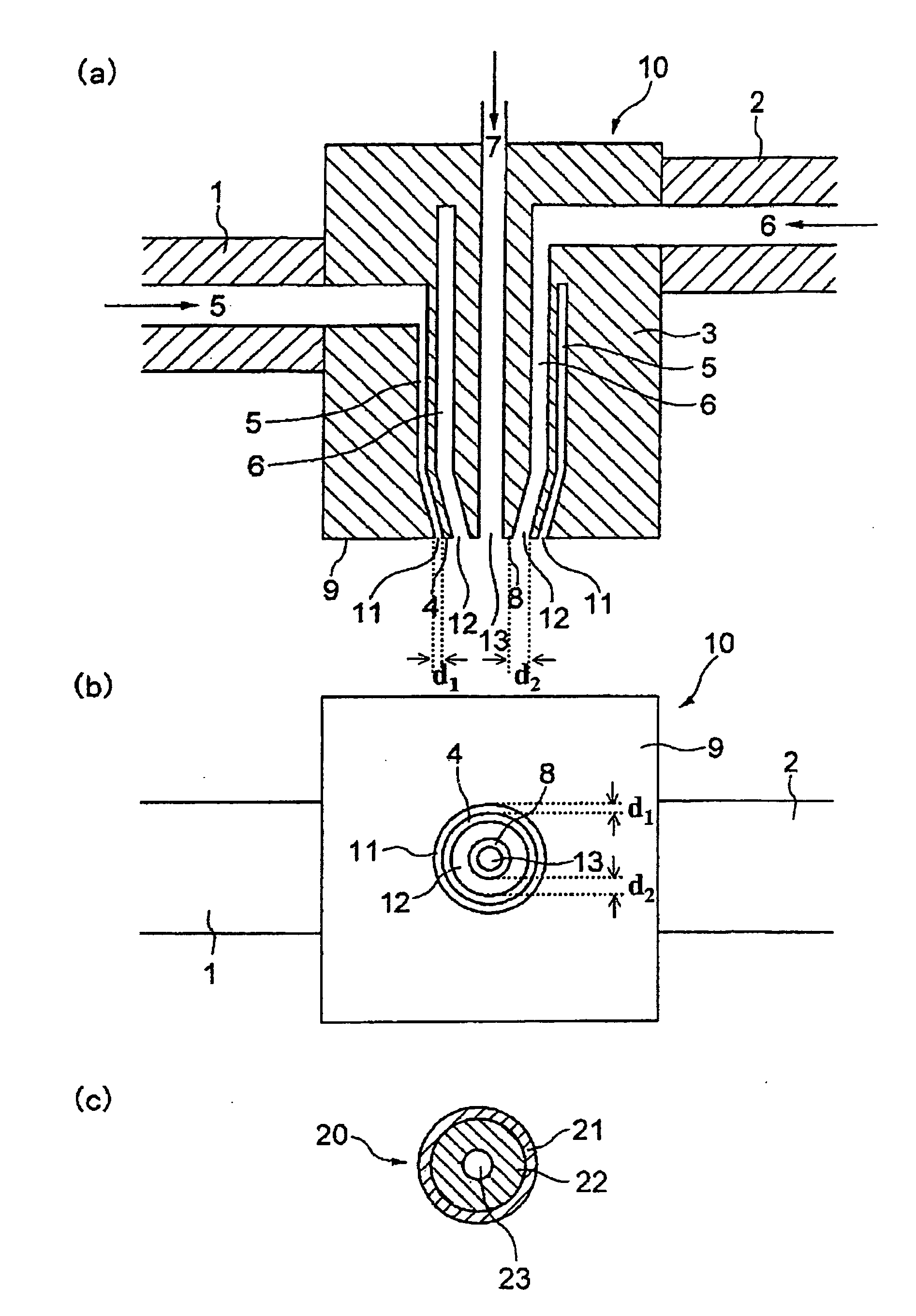
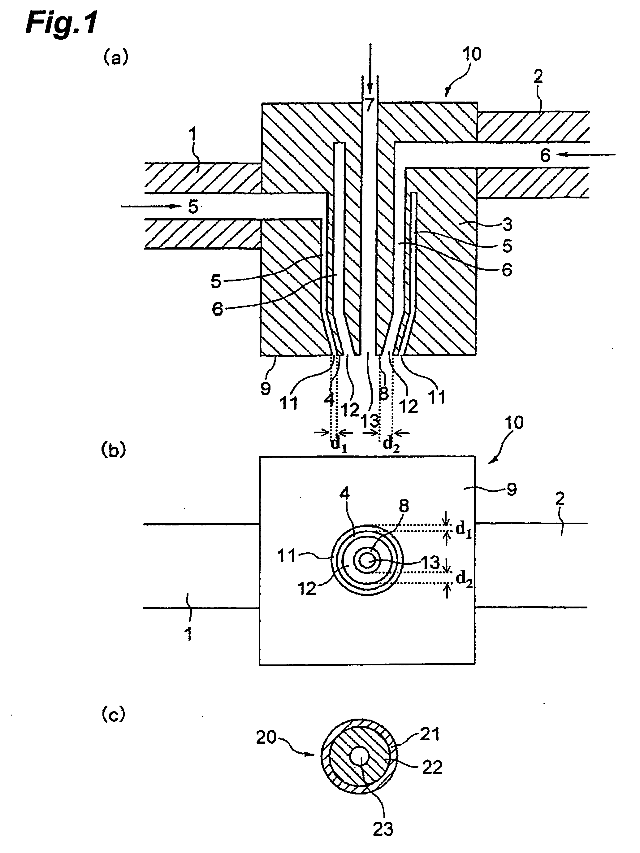
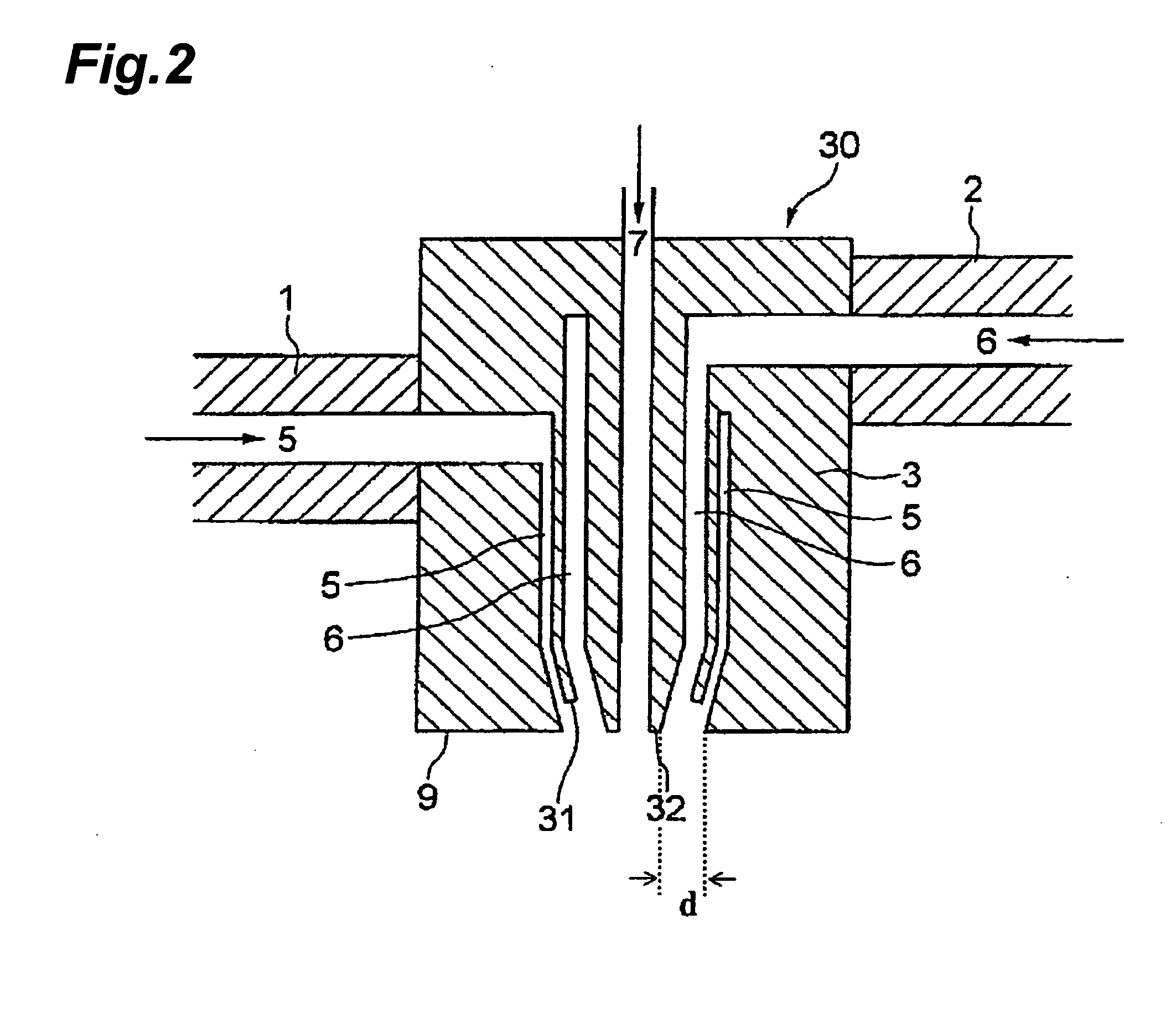
[0153]A vinylidene fluoride homopolymer was used as the thermoplastic resin, a mixture of di(2-ethylhexyl) phthalate and dibutyl phthalate was used as the organic liquid, and a silica fine powder was used as the inorganic fine powder. A two-layer hollow fiber membrane was melt-extruded using two extruders utilizing a hollow fiber molding nozzle shown in FIG. 2. An outer-layer molten mixture (a) had a composition in which vinylidene fluoride homopolymer: bis(2-ethylhexyl) phthalate: dibutyl phthalate: silica fine powder=40.0:30.8:6.2:23.0 (mass ratio) (volume ratio: 32.2:44.4:8.4:15). An inner-layer molten mixture (b) had a composition in which vinylidene fluoride homopolymer:bis(2-ethylhexyl) phthalate: dibutyl phthalate: silica fine powder=40.0:35.1:1.9:23.0 (mass ratio) (volume ratio: 32.0:50.0:2.6:14.9). Air was used as a hollow-portion-forming fluid. The molten mixture was extruded from a hollow fiber molding nozzle (outer diameter: 2.00 mm, inner diameter: 0.92 mm) at a resin temperature of 240° C. and a discharge linear velocity of 14.2 m/min (i.e., spinning nozzle discharge parameter R was 440/sec) so that the thickness ratio (outer layer:inner layer) was 10:90. The outer diameter of the nozzle refers to the outermost diameter of the discharge port in FIG. 2. The inner diameter of the nozzle refers to the maximum diameter of the lower end of the partition wall between the inner-layer molten mixture discharge port and the hollow-portion-forming fluid discharge port.
[0154]The extruded hollow fiber extruded product traveled over 60 cm in the air, and was introduced into a water bath at 40° C. to solidify the product. The product was wound around a reel at 40 m/min. The resulting two-layer hollow fiber was immersed in methylene chloride to remove bis(2-ethylhexyl) phthalate and dibutyl phthalate by extraction, and was then dried. The dried product was immersed in a 50 mass % ethanol aqueous solution for 30 minutes, immersed in water for 30 minutes, immersed in a 20 mass % sodium hydroxide aqueous solution at 70° C. for one hour, and then washed with water to remove the silica fine powder by extraction.
[0155]The resulting porous two-layer hollow fiber membrane did not show interface non-uniformity and had a high roundness. As a result of cross-sectional observation using an electron microscope, it was confirmed that the blocking layer and the support layer had an isotropic three-dimensional mesh structure without macro-voids. Table 2 shows the outer diameter, the inner diameter, the aspect ratio, the pure water permeation rate, the uniform latex sphere blocking rate, the breaking strength, the elongation at break, the compressive strength, the outer surface pore diameter (corresponding to the surface pore diameter of the layer (B)), the inner surface pore diameter (corresponding to the surface pore diameter of the layer (A)), the cross-sectional center pore diameter, the ratio of the outer surface pore diameter and the cross-sectional center pore diameter, the ratio of the inner surface pore diameter and the cross-sectional center pore diameter, and the degrees of isotropy of the layer (A) and the layer (B) of the resulting membrane. The porous two-layer hollow fiber membrane had a high pure water permeation rate, latex blocking rate, and mechanical strength.
[0156]The porous two-layer hollow fiber membrane was wetted by the method (2), and immersed in a 4 mass % sodium hydroxide aqueous solution containing sodium hypochlorite (free chlorine concentration: 0.5 mass %) at room temperature for 10 days. The elongation at break of the porous two-layer hollow fiber membrane was measured before and after immersion. The elongation at break after immersion was 90% of the elongation at break before immersion. It was confirmed that the porous two-layer hollow fiber membrane had excellent chemical resistance.
[0157]FIG. 6 shows an electron microscope image of the outer surface of the porous two-layer hollow fiber membrane at a magnification of 5000. FIG. 7 shows an electron microscope image of a portion around the outer surface of the cross section at a magnification of 5000. FIG. 8 shows an electron microscope image of a portion around the outer surface of the cross section at a magnification of 1000. FIG. 9 shows an electron microscope image of the center of the cross section at a magnification of 5000. FIG. 10 shows an electron microscope image of a portion around the inner surface of the cross section at a magnification of 5000. FIG. 11 shows an electron microscope image of the inner surface at a magnification of 5000. As is clear from the electron microscope images shown in FIGS. 6 to 11, the outer layer having a small pore diameter and the inner layer having a large pore diameter were formed in the porous two-layer hollow fiber membrane. The surface porosity of the layer (B) was 25%.
[0158]A small amount of graphite was mixed into the molten mixture (a) (outer layer) to obtain a two-layer hollow fiber (organic liquid was not removed). The entire outer surface of the two-layer hollow fiber was black. This indicates that the entire outer surface was covered with the molten mixture (a). A white area which indicates that the molten mixture (b) was exposed on the outer surface was not observed on the two-layer hollow fiber over 100 meters or more. FIG. 12 shows a microscope image of the circular cross section of the two-layer hollow fiber. As shown in FIG. 12, the black layer (layer of the molten mixture (a)) covered the outer surface in the cross-sectional direction to a uniform thickness without defects.

Example

Example 2
[0159]A porous two-layer hollow fiber membrane was obtained in the same manner as in Example 1 except for using an outer-layer molten mixture (a) having a composition in which vinylidene fluoride homopolymer: bis(2-ethylhexyl) phthalate: dibutyl phthalate: silica fine powder=34:33.8:6.8:25.4 (mass ratio) and an inner-layer molten mixture (b) having a composition in which vinylidene fluoride homopolymer:bis(2-ethylhexyl) phthalate:dibutyl phthalate:silica fine powder=36:35.3:5.0:23.7 (mass ratio).
[0160]FIG. 13 shows an electron microscope image of the outer surface of the porous two-layer hollow fiber membrane at a magnification of 5000. FIG. 14 shows an electron microscope image of a portion around the outer surface of the cross section at a magnification of 5000. FIG. 15 shows an electron microscope image of a portion around the outer surface of the cross section at a magnification of 1000. FIG. 16 shows an electron microscope image of the center of the cross section at a magnification of 5000. FIG. 17 shows an electron microscope image of a portion around the inner surface of the cross section at a magnification of 5000. FIG. 18 shows an electron microscope image of the inner surface at a magnification of 5000. FIG. 19 shows an electron microscope image of the cross section at a magnification of 60. FIG. 20 shows an electron microscope image of the cross section at a magnification of 300. As is clear from the electron microscope images shown in FIGS. 13 to 20, the outer layer having a small pore diameter and the inner layer having a large pore diameter were formed in the porous two-layer hollow fiber membrane. The surface porosity of the layer (B) was 30%.
[0161]The resulting porous two-layer hollow fiber membrane did not show interface non-uniformity and had a high roundness. As a result of cross-sectional observation using an electron microscope, it was confirmed that the blocking layer and the support layer had an isotropic three-dimensional mesh structure without macro-voids. The property evaluation results of the resulting membrane are shown in Table 2. The porous two-layer hollow fiber membrane had a high pure water permeation rate, latex blocking rate, and mechanical strength. FIG. 21 shows the measurement results for the cross-sectional pore diameter when equally dividing the cross section of the porous two-layer hollow fiber membrane into 100 sections. The porous two-layer hollow fiber membrane had a structure very similar to that shown in FIG. 5(3). FIG. 33 shows the measurement results for the parameter Q.

Example

Example 3
[0162]A porous two-layer hollow fiber membrane was obtained in the same manner as in Example 1 except for using an outer-layer molten mixture (a) having a composition in which vinylidene fluoride homopolymer:(2-ethylhexyl) phthalate:dibutyl phthalate=40.0:36.0:24.0 (mass ratio).
[0163]The resulting porous two-layer hollow fiber membrane did not show interface non-uniformity and had a high roundness. As a result of cross-sectional observation using an electron microscope, it was confirmed that the blocking layer and the support layer had an isotropic three-dimensional mesh structure without macro-voids. The property evaluation results of the resulting membrane are shown in Table 2. The porous two-layer hollow fiber membrane had a high pure water permeation rate, latex blocking rate, and mechanical strength.

PUM

PropertyMeasurementUnit
Fraction0.8fraction
Pore size0.1μm
Pore size10.0μm
tensileMPa
Particle sizePa
strength10

Description & Claims & Application Information

We can also present the details of the Description, Claims and Application information to help users get a comprehensive understanding of the technical details of the patent, such as background art, summary of invention, brief description of drawings, description of embodiments, and other original content. On the other hand, users can also determine the specific scope of protection of the technology through the list of claims; as well as understand the changes in the life cycle of the technology with the presentation of the patent timeline. Login to view more.

Similar technology patents

Prepreg, laminate, and molding

PendingUS20220213284A1Excellent strengthReduce molding time and molding costLayered productsVehicle componentsPolymer chemistryTensile shear
Owner:TORAY IND INC

Molybdenum-tungsten alloy and preparation method thereof

InactiveCN106435413AExcellent strengthChromium sesquioxideYttrium
Owner:林海英

Classification and recommendation of technical efficacy words

  • High water permeability
  • Excellent strength

Photocatalyst Particle Body

InactiveUS20070275851A1High water permeabilityExcellent network structureCatalyst protectionWater/sewage treatment by irradiationPhotocatalysisBody size
Owner:SASANO DENSEN

Permeable pavement brick

InactiveCN105200893AHigh water permeabilityGood water permeabilitySidewalk pavingsWave troughWave crest
Owner:ANHUI HUAPU ENERGY SAVING MATERIALS

Gas deep dehumidification film and preparation method thereof

Owner:LIAONING UNIVERSITY OF PETROLEUM AND CHEMICAL TECHNOLOGY

Method for manufacturing molded foam

ActiveUS20110101558A1Excellent strengthSemi-permeable membranesHollow wall articlesComposite materialShell molding
Owner:KYORAKU CO LTD
Why Eureka
Try Eureka