Conductive elastic roller and image forming apparatus comprising the same

a technology of conductive elastic rollers and image forming apparatuses, which is applied in the direction of shafts and bearings, corona discharge, instruments, etc., can solve the problems of large heat energy requirements, considerable time and other issues, and achieve the effects of small residual strain, improved stain resistance to an adjoining member, and low hardness

Active Publication Date: 2010-01-21
ARCHEM INC
View PDF10 Cites 10 Cited by
  • Summary
  • Abstract
  • Description
  • Claims
  • Application Information

AI Technical Summary

Benefits of technology

[0029]According to the invention, there can be provided a conductive elastic roller provided with an elastic layer(s) having a low hardness, a small compression residual strain and an improved stain resistance to an adjoining member such as Organic Photoconductors or the like and capable of producing in a short time without requiring a large quantity of heat energy and considerable expense for equipment by curing a raw material for the elastic layer comprising a urethane acrylate oligomer (A) synthesized by using a polyether polyol (a1) having a proportion of primary hydroxyl groups in hydroxyl groups located at molecular ends of not less than 40%, a photo-polymerization initiator (B) and a conductive agent (C) through ultraviolet irradiation to form at least one of the elastic layers. Furthermore, there can be provided a c...

Problems solved by technology

However, when the thermosetting urethane resin or the like is used in the elastic layer to produce the conductive elastic roller, it is necessary to cure the resin material under heating, so that a large quantity of heat energy is required and a considerable time is also required in the curing.
Further, there is a problem that considerable expense for equipment such as a curing furnace or the like is required for conducting the heat curing.
When the roller provided with the elastic layer having high staining properties to the adjoining member is used as a developing roller or the like in an image forming apparatus, it stains an adjoining member such as Organic Photoconductors or the like, and hence a bad imaging is ...

Method used


Image

  • Conductive elastic roller and image forming apparatus comprising the same
  • Conductive elastic roller and image forming apparatus comprising the same

Examples


example 1

[0072]100 parts by mass of bifunctional polyether polyol having a proportion of primary hydroxyl groups in hydroxyl groups located at molecular ends of 70% obtained by an addition polymerization of propylene oxide to propylene glycol [PRIMEPOLE PX-1000 made by Sanyo Chemical Industries, Ltd., weight average molecular weight: 1000, hydroxyl value: 111 mg KOH / g], 27.49 parts by mass of isophorone diisocyanate [isocyanate group / hydroxyl group of polyol=5 / 4 (molar ratio)] and 0.01 part by mass of dibutyltin dilaurate are reacted at 70° C. for 2 hours while mixing under heating with stirring to synthesize a urethane prepolymer having isocyanate groups at both ends of its molecular chain. Furthermore, 100 parts by mass of the urethane prepolymer are reacted with 5.73 parts by mass of 2-hydroxyethyl acrylate (HEA) at 70° C. for 2 hours while mixing with stirring to synthesize a urethane acrylate oligomer (A-1) having a molecular weight of 5000 (calculated value).

[0073]60.0 parts by m...

example 2

[0077]100 parts by mass of polyether polyol made by Sanyo Chemical Industries, Ltd., “PRIMEPOLE PX-1000”, 25.66 parts by mass of isophorone diisocyanate [isocyanate group / hydroxyl group of polyol=7 / 6 (molar ratio)] and 0.01 parts by mass of dibutyltin dilaurate are reacted at 70° C. for 2 hours while mixing under heating with stirring to synthesize a urethane prepolymer having isocyanate groups at both ends of its molecular chain. Furthermore, 100 parts by mass of the urethane prepolymer are reacted with 3.82 parts by mass of 2-hydroxyethyl acrylate at 70° C. for 2 hours while mixing with stirring to synthesize a urethane acrylate oligomer (A-2) having a molecular weight of 8000 (calculated value).

[0078]50.0 parts by mass of the urethane acrylate oligomer (A-2), 40.0 parts by mass of an acrylate monomer made by Kyoei-Sha Chemical Co., Ltd., “LIGHT-ACRYLATE IM-A”, 10.0 parts by mass of an acrylate monomer made by SHIN-NAKAMURA CHEMICAL CO., LTD., “NK ESTER A-SA”, 0.5 parts by mas...

example 3

[0082]70 parts by mass of polyether polyol made by Sanyo Chemical Industries, Ltd., “PRIMEPOLE PX-1000”, 30.0 parts by mass of an acrylate monomer made by Kyoei-Sha Chemical Co., Ltd., “LIGHT-ACRYLATE IM-A”, 17.96 parts by mass of isophorone diisocyanate [isocyanate group / hydroxyl group of polyol=7 / 6 (molar ratio)] and 0.01 parts by mass of dibutyltin dilaurate are reacted at 70° C. for 2 hours while mixing under heating with stirring to synthesize a urethane prepolymer having isocyanate groups at both ends of its molecular chain. Furthermore, 100 parts by mass of the urethane prepolymer are reacted with 2.68 parts by mass of 2-hydroxyethyl acrylate at 70° C. for 2 hours while mixing with stirring to synthesize a urethane acrylate oligomer (A-3) having a molecular weight of 8000 (calculated value).

[0083]80.0 parts by mass of the urethane acrylate oligomer (A-3), 10.0 parts by mass of an acrylate monomer made by Kyoei-Sha Chemical Co., Ltd., “LIGHT-ACRYLATE IM-A”, 10.0 parts by m...


PUM


Abstract

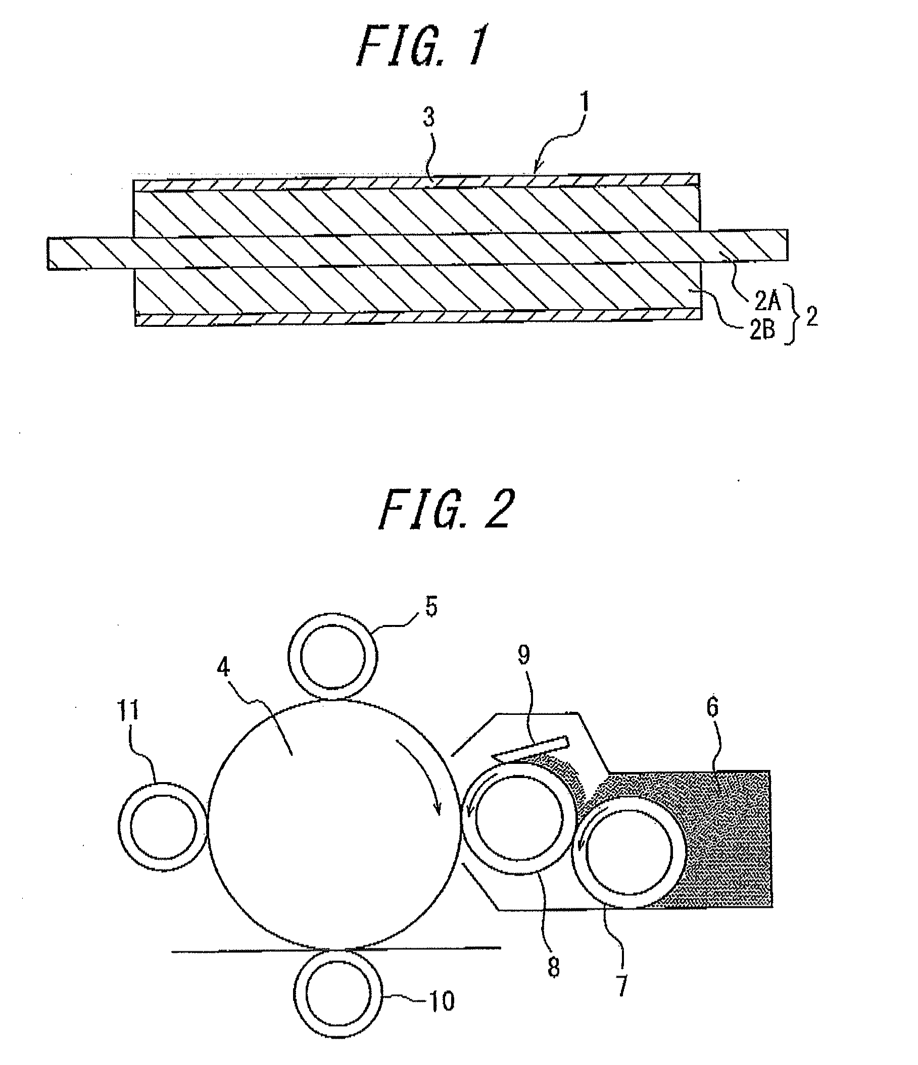
This invention is a conductive elastic roller (1) comprising a shaft member (2) and one or more elastic layers (3) disposed on an outside of the shaft member (2) in a radial direction, wherein at least one of the elastic layers (3) is composed of an ultraviolet-curing type resin formed by curing a raw material for the elastic layer comprising a urethane acrylate oligomer (A), a photo-polymerization initiator (B) and a conductive agent (C) through ultraviolet irradiation, and the urethane acrylate oligomer (A) is a urethane acrylate oligomer synthesized by using as a polyol a polyether polyol (a1) having a proportion of primary hydroxyl groups in hydroxyl groups located at molecular ends of not less than 40% obtained by an addition polymerization of propylene oxide to a polyhydric alcohol alone, or the polyether polyol (a1) and another polyol (a2), and provides a conductive elastic roller (1) provided with an elastic layer having a low hardness, a small compression residual strain and an improved stain resistance to an adjoining member such as Organic Photoconductors or the like.

Description

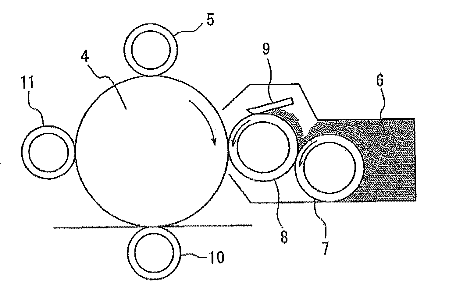
TECHNICAL FIELD[0001]This invention relates to a conductive elastic roller and an image forming apparatus comprising such a conductive elastic roller, and more particularly to a conductive elastic roller provided with an elastic layer having a low hardness and an improved stain resistance to an adjoining member such as Organic Photoconductors or the like.BACKGROUND ART[0002]In general, a roll-shaped conductive elastic member or a conductive elastic roller is frequently used as a developing roller, a charging roller, a toner feed roller, a transfer roller, a paper feed roller, a cleaning roller, a pressure roller for fixing or the like in an image forming apparatus of an electro-photographic system such as a copying machine, a facsimile, a laser beam printer (LBP) or the like. Typically, the conductive elastic roller comprises a shaft member journaled at both longitudinal end portions thereof and at least one elastic layer disposed on an outside of the shaft member in a radial direct...

Claims


Application Information

Patent Timeline
IPC IPC(8): G03G15/02
CPCG03G15/0233G03G15/2057G03G15/1685G03G15/0818G03G15/20
Inventor SAKATA, JUNJI
Owner ARCHEM INC
Why Eureka
Try Eureka