
Intravascular Measurement

a technology of intravascular measurement and sensor, which is applied in the field of implantable sensors, can solve the problems of affecting the health of patients, affecting the flow of blood, and affecting the quality of life of patients, and achieves the effects of reducing the risk of thrombosis

Inactive Publication Date: 2010-01-28
BIOTRONIK VI PATENT
View PDF13 Cites 7 Cited by
  • Summary
  • Abstract
  • Description
  • Claims
  • Application Information

AI Technical Summary

Benefits of technology

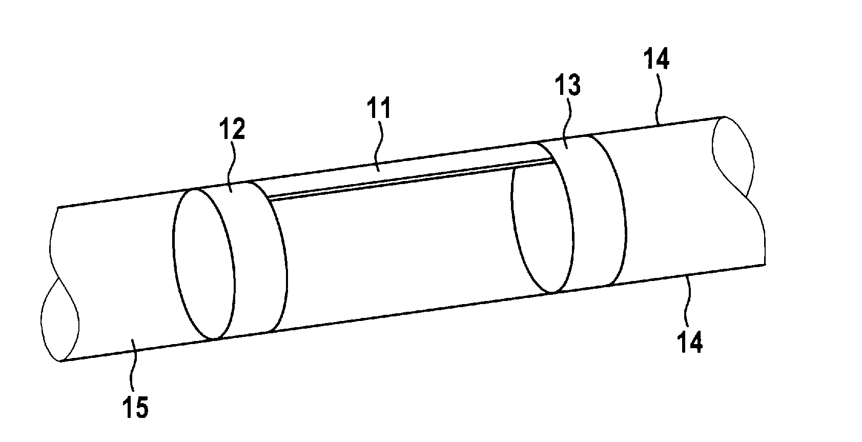
[0008]The present invention provides an implantable sensor for measurement of fluidic parameters, having a surface acoustic wave transponder (SAW transponder) for detection of vasomotor parameters and having a retaining stent, which is attached at two opposite ends of the surface acoustic wave transponder. The term “retaining stent” here means a stent-like retaining element, although it need not have the radial strength desired with a traditional stent but instead serves only to secure the surface acoustic wave transponder on the wall of the blood vessel. In particular, the retaining stents may also be shorter than traditional stents and may have a much lower radial strength.
[0010]The surface acoustic wave transponder at the same time allows the vasomotor quantity to be determined and read out without requiring a telemetry unit and thus a power supply by battery or induction. For this reason, the implantable sensor may be used independently of an electromedical implant such as a cardiac pacemaker and has small dimensions which help to prevent an impairment of blood flow. Use of the surface acoustic wave transponder as a sensor in a blood vessel also has the additional advantage that growth of cells covering the sensor does not impair the quality of the measurement. The blood pressure measurement can be calibrated by a reference measurement using traditional means. This reference measurement should be repeated at regular intervals because the measurement conditions can alter ingrowth of the sensor.
[0011]The surface acoustic wave transponder is pressed against the wall of the blood vessel because of the two retaining stents attached at the ends of the surface acoustic wave transponder, which is why the blood flow through the blood vessel is only slightly hindered because the lumen of the blood vessel remains essentially free. Furthermore, the entire surface acoustic wave transponder grows into the vascular wall over time, so there is practically no longer a risk of thrombosis, which is also why the aforementioned long-term burden of anticoagulant medication is also eliminated. According to an especially preferred embodiment of the invention, retaining stents made of a biocorrodible material, i.e., a material that can be degraded in the body over time, are also provided. The time during which the retaining stents are degraded as expected should be selected so that complete ingrowth of the surface acoustic wave transponder into the vascular wall is ensured before the retaining stents are degraded and / or are no longer able to affix the surface acoustic wave transponder to the vascular wall. In this embodiment the impairment in blood flow due to the blood pressure sensor is minimized after degradation of the retaining stent.
[0016]The readout of the surface acoustic wave transponder may take place up to a thousand times per second. Since a heartbeat occurs at the rate of approximately one beat per second, the measurement results collected over a period of 10 to 250 ms, for example, may be averaged to improve the measurement accuracy. Since the propagation rate of the surface wave in the transponder is also much higher than that of the pressure wave caused by the heartbeat in the blood vessel, the variations in blood pressure between two heartbeats over time can be determined, so that the systolic and diastolic blood pressure can easily be determined from the transient measurement.
[0022]The implantable sensor may be provided with a marker which allows easy location by means of X-ray or MRT.

Problems solved by technology

However, such sensors have the disadvantage that they hinder blood flow and also constitute a significant risk of thrombosis in addition to the exacerbating effect on circulation because cells or blood platelets or other solid components of blood may be deposited on such sensors.
If such a deposit is entrained by the blood flow away from the pressure sensor, it may result in a hazardous health impairment.
This risk is therefore counteracted by anticoagulants, i.e., administration of medication to prevent coagulation, although that also entails corresponding risks and adverse effects.
Furthermore, pressure sensors situated directly in the blood flow have the disadvantage that the deposits described above may lead to a considerable technical impairment of the sensor, even resulting in total failure.

Method used


Image

  • Intravascular Measurement
  • Intravascular Measurement

Examples


Embodiment Construction

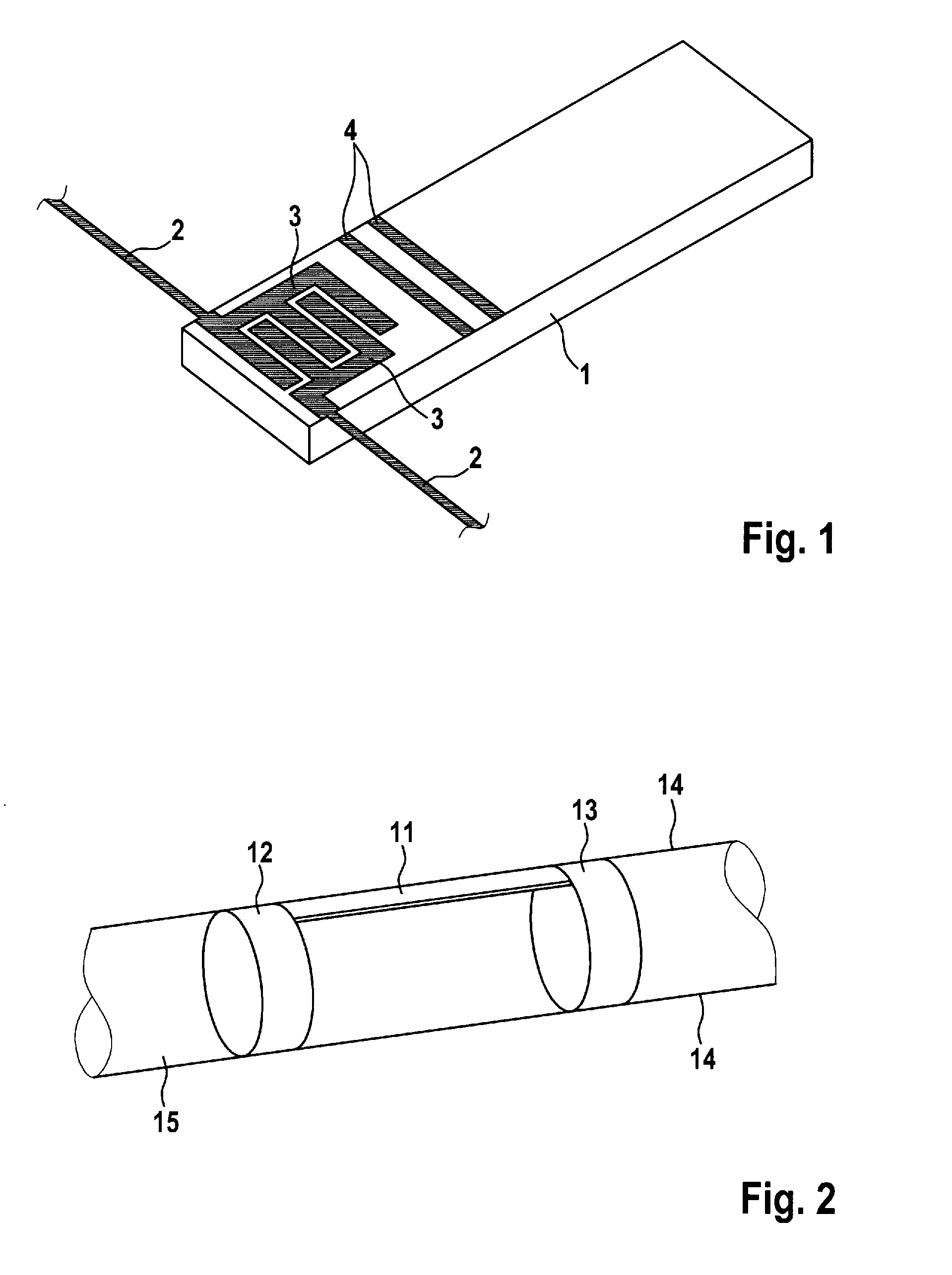
[0026]FIG. 1 shows a schematic diagram of a surface acoustic wave transponder. At one end of the carrier 1, interdigital converters 3 connected to an antenna 2 are applied to a carrier 1 consisting of a piezoelectric single crystal; these interdigital converters 3 have a toothed structure and generate a surface wave in the carrier 1 based on the force of the electromagnetic field which occurs on reception of a query pulse via the antenna 2 and acts on the piezoelectric material of the carrier 1. The antenna 2 here is embodied as a divided half-wave dipole, so the interdigital converters 3 pick up the received signal at the center of the antenna 2. The surface wave passes through the carrier 1, where it is exposed to influences due to changes in the path length due to deformation of the carrier 1 and based on elastic crystal constants. Two reflectors 4 are mounted on the carrier 1, generating reflections of the surface wave with a certain interval between them based on the fixed dist...


PUM


Abstract

An implantable sensor for measuring fluidic parameters with a surface acoustic wave transponder for detecting vasomotor quantities and one retaining stent attached to each of two opposite ends of the surface acoustic wave transponder.

Description

CROSS-REFERENCE TO RELATED APPLICATIONS[0001]This application claims benefit of priority to German patent application number 10 2008 040 790.9, filed Jul. 28, 2008; the contents of which are herein incorporated by reference in their entirety.FIELD OF THE INVENTION[0002]The invention relates to an implantable sensor for detection of fluidic characteristics of blood flow.BACKGROUND OF THE INVENTION[0003]Implantable pressure sensors which can be placed in a blood vessel and allow a determination of the blood pressure are known in the prior art. The measurement results of such pressure sensors are used to monitor cardiac output of patients with cardiac insufficiency or similar conditions. Such a pressure sensor is disclosed in US 2002 / 0045921, for example.[0004]Telemetry units are frequently used to read out the values determined by the implantable pressure sensor; for example, after activation of a magnetic switch situated in or connected to the pressure sensor by a reading head, these...

Claims


Application Information

Patent Timeline
Patent Type & Authority Applications(United States)
IPC IPC(8): A61B5/02
CPCA61B5/0215A61B5/6862A61B2562/164A61B5/6882A61B2560/0219A61B5/6876
Inventor TITTELBACH, MICHAELHARDER, CLAUS
Owner BIOTRONIK VI PATENT
Learn More