Tool Tips with Scanning Probe Microscopy and/or Atomic Force Microscopy Applications

a scanning probe and microscopy technology, applied in the field of microobject manufacturing and processing, can solve the problems of limiting the use of special high-performance materials, long tool pieces, and insufficient tool head length, so as to achieve the effect of reducing tooling costs and high performan

Inactive Publication Date: 2010-02-04
KLEY VICTOR B
View PDF79 Cites 19 Cited by
  • Summary
  • Abstract
  • Description
  • Claims
  • Application Information

AI Technical Summary

Benefits of technology

[0012]It is yet another desirable outcome to be able to define tool pieces or tips whose length is very large compared to the tool body and millimeters for bodies whose width is only a few tens of microns. It is desirable to make tool bodies with integrated tip pieces for various precise and special applications such as indentation by limiting the secondary shaping or sharpening of the tool piece to the minimum material removal consistent with the application.
[0015]Yet another aim of some embodiments of this invention is to configure custom systems at very high performance and minimum tooling costs to test semiconductor chips, biochips and special operations such as inserting or removing material from wells for chemical, biological or material testing or evaluation and development.
[0018]By forming the entire tool body and tool piece from one slab of material whose thickness closely approximates the desired width of the cantilever a broad range of different designs can be implemented with minimum cost and tool development. Further a special shape can be designed and then material such as CVD diamond coated on the shape such that final finishing by other means such as lithographic wet or dry etching, ion milling and / or additions, electron beam milling and / or chemical mediation to add or subtract material, and / or nanolapping, and / or lapping and / or polishing and / or grinding or conventional machining including water jetting may be used alone or in combination to make the particular desired forms.

Problems solved by technology

Execution of present methods for handling, aligning and mounting small structures, particularly structures smaller then 200 microns (referred to as micro-objects), is highly difficult and often results in uncertain orientation of the fine tool head structure relative to the tool body.
Present methods for cantilever and tip manufacture also limit the length of tool pieces and make it necessary to provide substantial extra unused material in the tool head which can be expensive and limiting in the use of special high performance materials.

Method used


Image

  • Tool Tips with Scanning Probe Microscopy and/or Atomic Force Microscopy Applications
  • Tool Tips with Scanning Probe Microscopy and/or Atomic Force Microscopy Applications
  • Tool Tips with Scanning Probe Microscopy and/or Atomic Force Microscopy Applications

Examples


Embodiment Construction

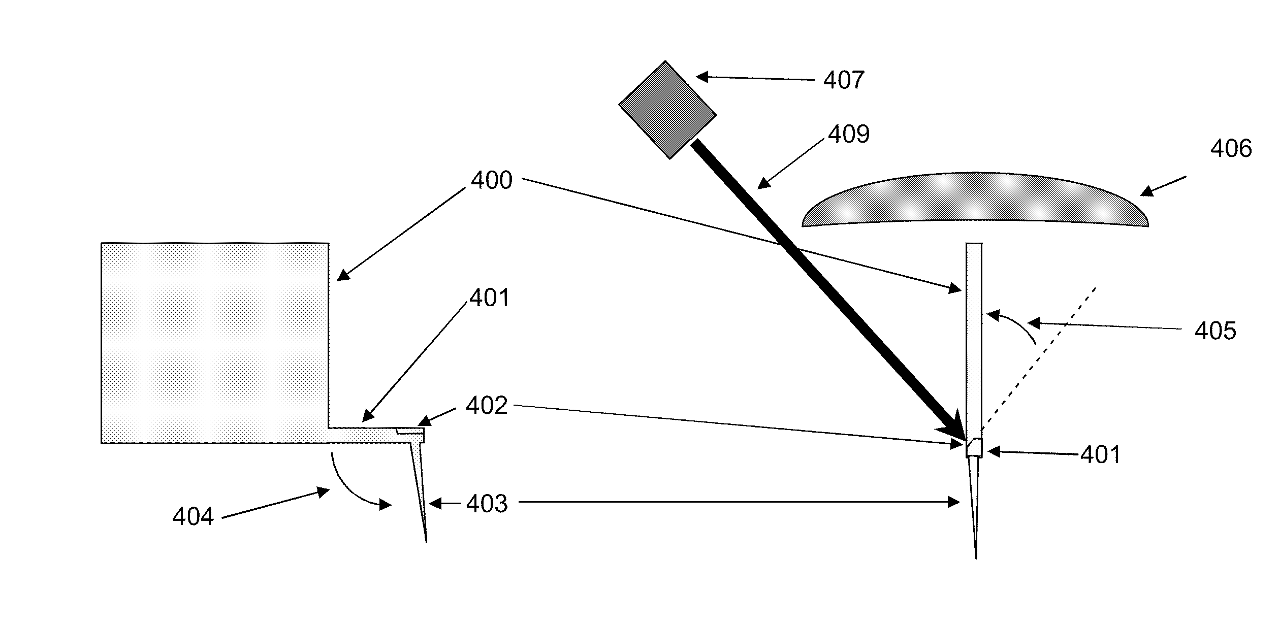
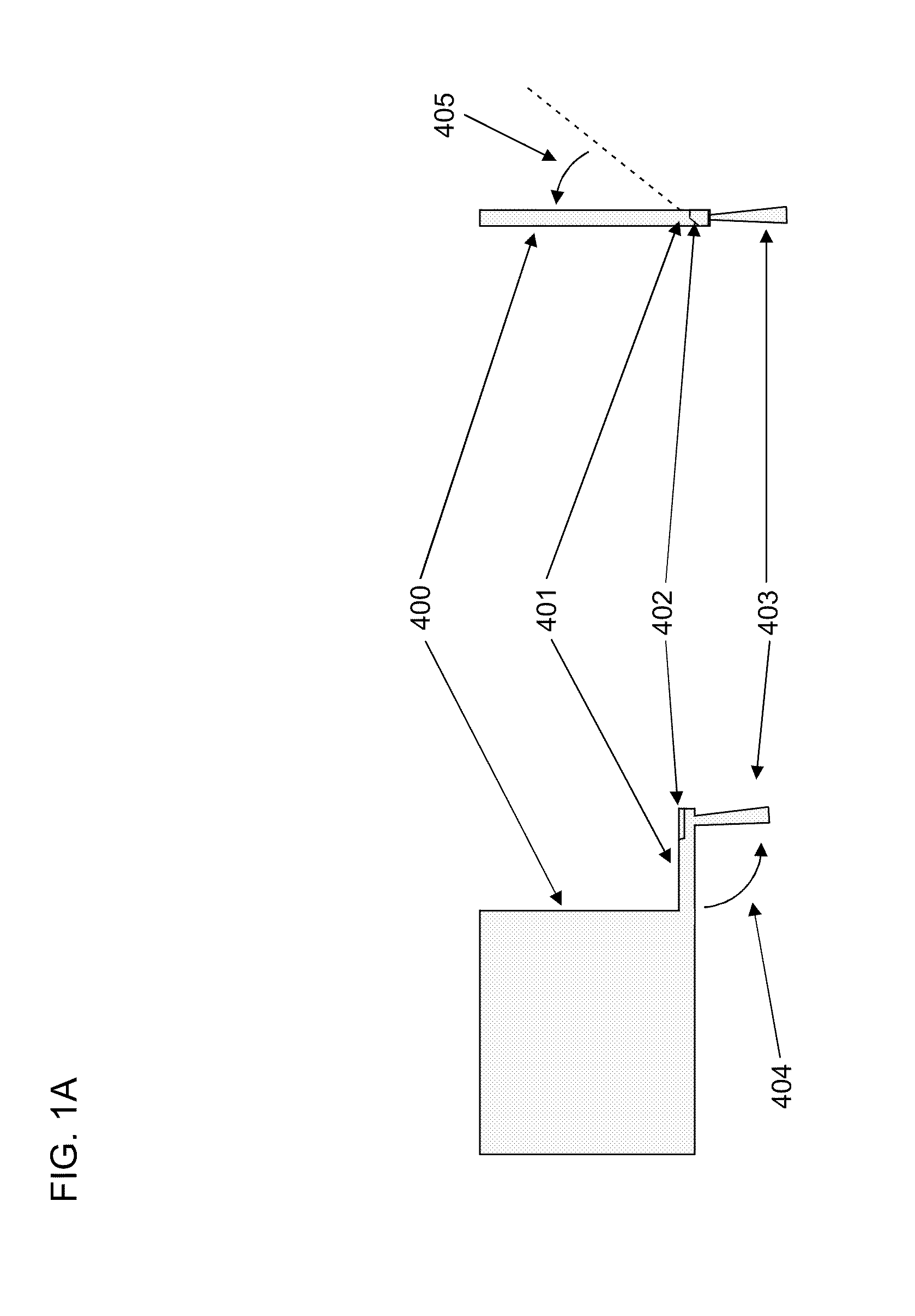
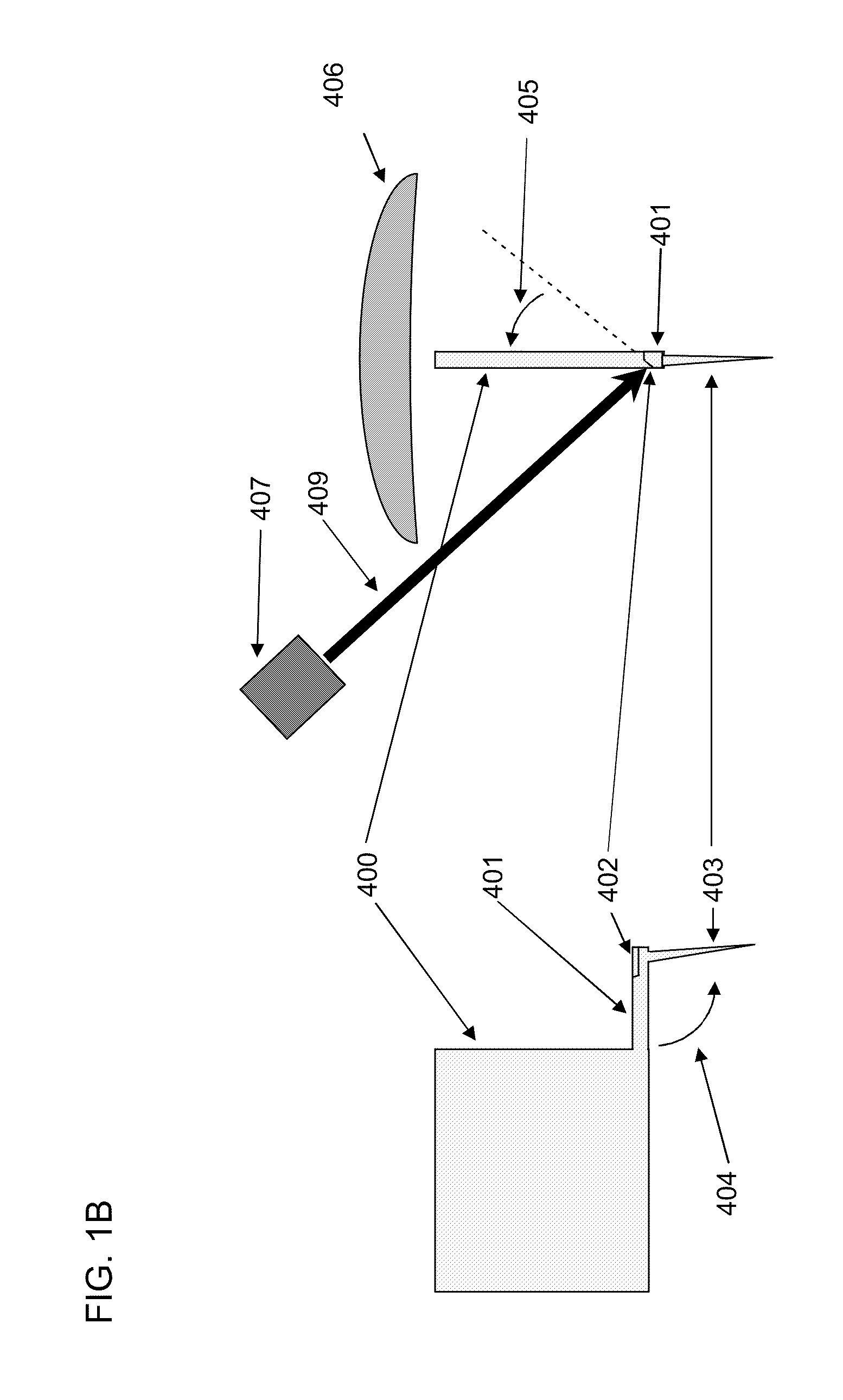
[0075]FIG. 1A shows a body 400, cantilever 401 with angled reflecting surface 402 and tip 403 formed by etching, wet or dry, laser cutting, ion milling / addition, electron beam mediated chemical milling / addition, direct electron beam milling, coating by any means, machining, abrasive water jet, or grinding, lapping and polishing or any combination of the latter methods in single crystal silicon 100, single crystal silicon 110 or any single crystal silicon orientation appropriate to the desired structure, or in amorphous or polycrystalline silicon, silicon carbide, single crystal diamond, polycrystalline or nanocrystalline diamond or amorphous diamond, boron nitride, boron carbide, tungsten nitride, tungsten carbide, single crystal or amorphous quartz, glass, sapphire, metals, alloyed metals, plastics, ceramics, or composites,

[0076]In one embodiment the integrated structure composed of 400, 401, 402 and 403 is formed by a combination of wet etching and dry etching of single crystal si...


PUM

PropertyMeasurementUnit
angleaaaaaaaaaa
lengthaaaaaaaaaa
lengthsaaaaaaaaaa

Abstract

A micro-object is affixed to a mounting structure at a desired relative orientation. The micro-object may be a tool tip optimized to work with particular microscope objectives permitting the tip to be imaged along with the object surface and used to make measurements or modifications through a travel range along the microscope imaging axis equal to or nearly equal to the working distance of the given objective. The tool tip may have a lengths exceeding 80 microns, say up to several millimeters; even the longest tips can have widths of tens of microns.

Description

CROSS-REFERENCES TO RELATED APPLICATIONS[0001]This application is a division of U.S. patent application Ser. No. 11 / 531,248, filed Sep. 12, 2009, entitled “Tool Tips with Scanning Probe Microscopy and / or Atomic Force Microscopy Applications,” now U.S. Pat. No. 7,571,638, issued Aug. 11, 2009, which is a continuation-in-part of U.S. patent application Ser. No. 11 / 3 82,651, filed May 10, 2006, entitled “Tool Tips with Scanning Probe Microscopy and / or Atomic Force Microscopy Applications,” which claims the benefit of each of the following four U.S. Provisional Applications:[0002]Application No. 60 / 679,926, filed May 10, 2005, entitled “Manufacturing of Micro-Objects Such as Miniature Diamond Tool Tips”;[0003]Application No. 60 / 698,356, filed Jul. 11, 2005, entitled “Manufacturing of Micro-Objects Such as Miniature Diamond Tool Tips”;[0004]Application No. 60 / 707,840, filed Aug. 11, 2005, entitled “Manufacturing of Micro-Objects Such as Miniature Diamond Tool Tips”; and[0005]Application ...

Claims


Application Information

Patent Timeline
Patent Type & Authority Applications(United States)
IPC IPC(8): G01Q70/08G01Q70/00B29C33/38
CPCB82Y15/00B82Y35/00G01Q60/38G01Q30/02G01Q70/12G01Q20/02G01Q70/10
Inventor KLEY, VICTOR B.
Owner KLEY VICTOR B
Why Eureka
Try Eureka