Polyamide electrical insulation for use in liquid filled transformers

Active Publication Date: 2010-02-18
WEINBERG MARTIN
View PDF18 Cites 4 Cited by
  • Summary
  • Abstract
  • Description
  • Claims
  • Application Information

AI Technical Summary

Benefits of technology

[0021]Many technically used synthetic polyamides are derived from monomers containing 6-12 carbon atoms; most prevalent are PA6 and PA66. The amide groups in the mostly semi crystalline polyamides are capable of forming strong electrostatic forces between the —NH and the —CO— units (hydrogen bonds), producing high melting points, exceptional strength and stiffness, high barrier properties and excellent chemical resistance. Moreover, the amide units also form strong interactions with water, causing the polyamides to absorb water. These water molecules are inserted into the hydrogen bonds, loosening the intermolecular attracting forces and acting as a plasticizer, resulting in the exceptional toughness and elasticity.
[0022]The subject electrical insulation of this invention, upon exposure to moisture, shows an increase in toughness and elongation. Long term exposure to moisture produces no negative aging effects. The subject material will absorb moisture, removing it from the surrounding oil, which may be a positive effect.
[0023]As the subject material does not need to be dried before use, it does not have the initial shrinkage issues of the current art. Further, exposure to elevated transformer temperatures and moisture will not cause embrittlement. The transformer will not be subject to problems of reduced winding compactness. Additionally, due to the high tensile strength and elongation memory of the subject material, turn insulation will remain tightly wrapped to the conductor wire. In addition, the stress-induced crystallinity of the film embodiment of the invention will provide improved long term dimensional stability.
[0024]The subject material film embodiment of the invention has a K factor (standard of thermal conductance=W/(m·K)) of 0.25. Oil impregnated cellulosic material has a K factor of approximately 0.10 (based on 50% oil saturation). Further, the subject material has a dielectric strength approximately 2× that of oil impregnated cellulosic insulation of equal thickness, requiring approximately half the thickness in turn in

Problems solved by technology

Moreover, the amide units also form strong interactio

Method used


Image

  • Polyamide electrical insulation for use in liquid filled transformers
  • Polyamide electrical insulation for use in liquid filled transformers
  • Polyamide electrical insulation for use in liquid filled transformers

Examples


Embodiment Construction

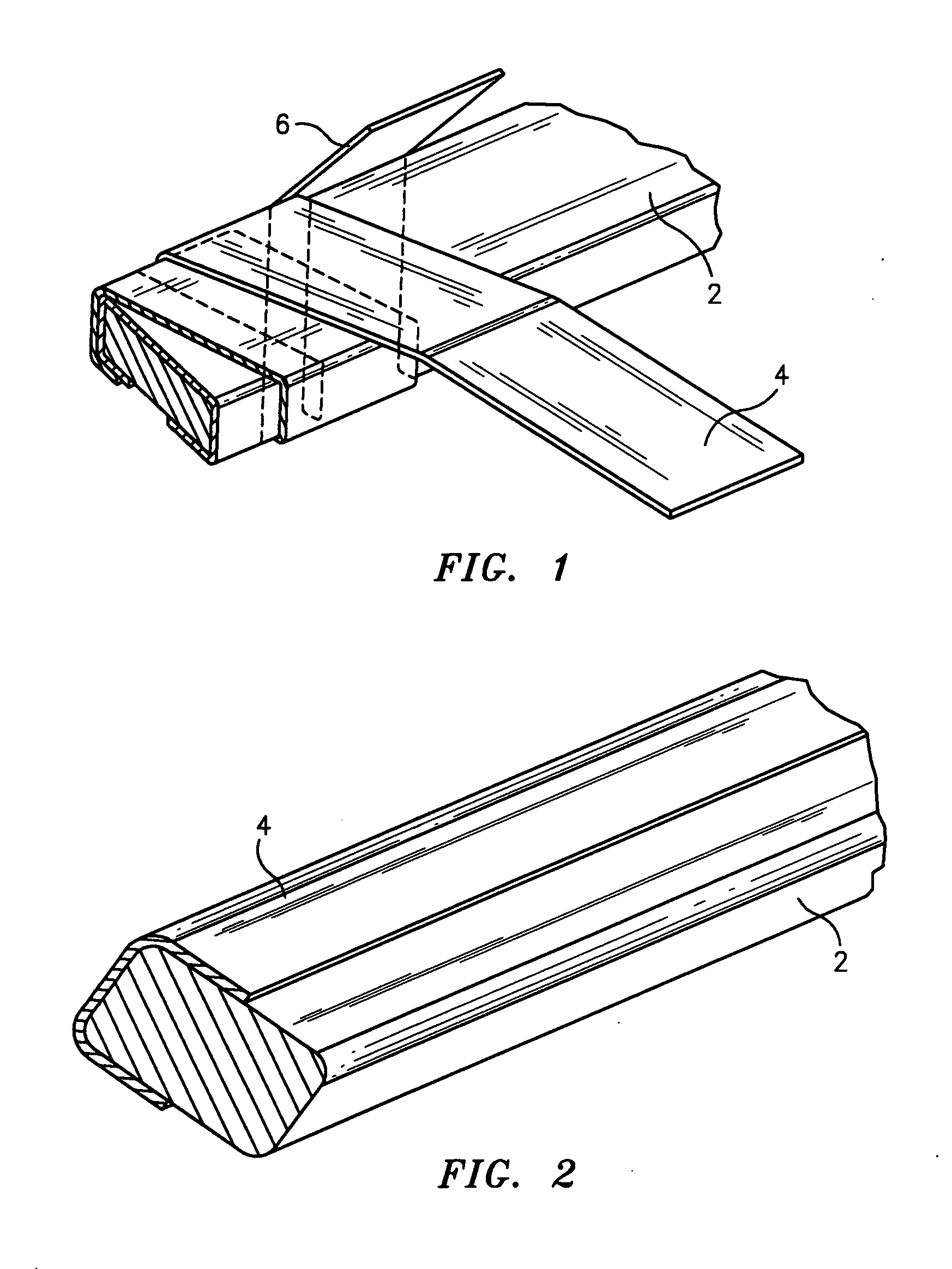
[0037]Referring now to the drawings, FIGS. 1 and 2 show two different forms of insulated magnet wire 2 that can be used for oil filled transformer coils. These magnet wires are insulated with aliphatic polyamide insulation tapes 4 and 6 which are formed in accordance with this invention. FIG. 1 shows a spirally wrapped magnet wire 2 wherein the insulation tapes 4 and 6 are spirally wrapped about the magnet wire 2 in a known manner. FIG. 2 shows a linear wrapped magnet wire 2 that can be used for oil filled transformer coils. These magnet wires are also insulated with aliphatic polyamide insulation tape 4 which is formed in accordance with this invention.

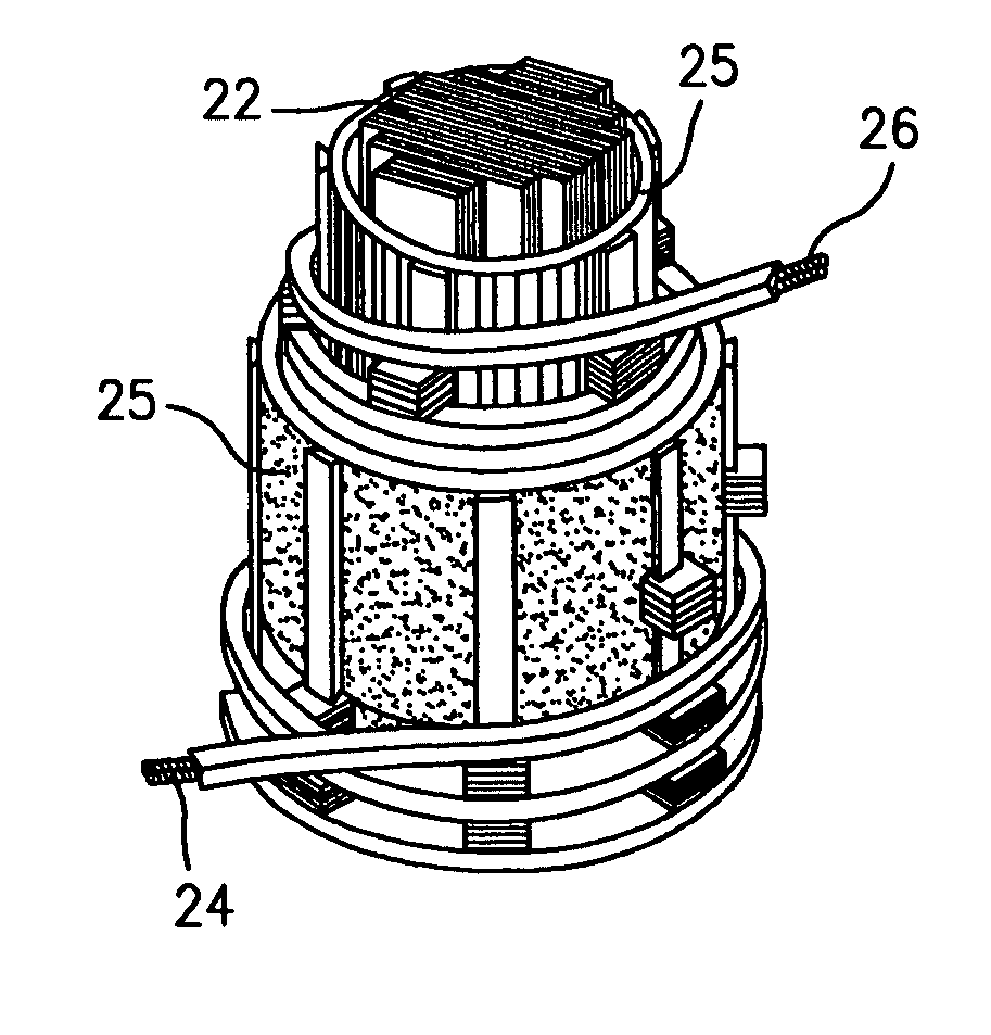
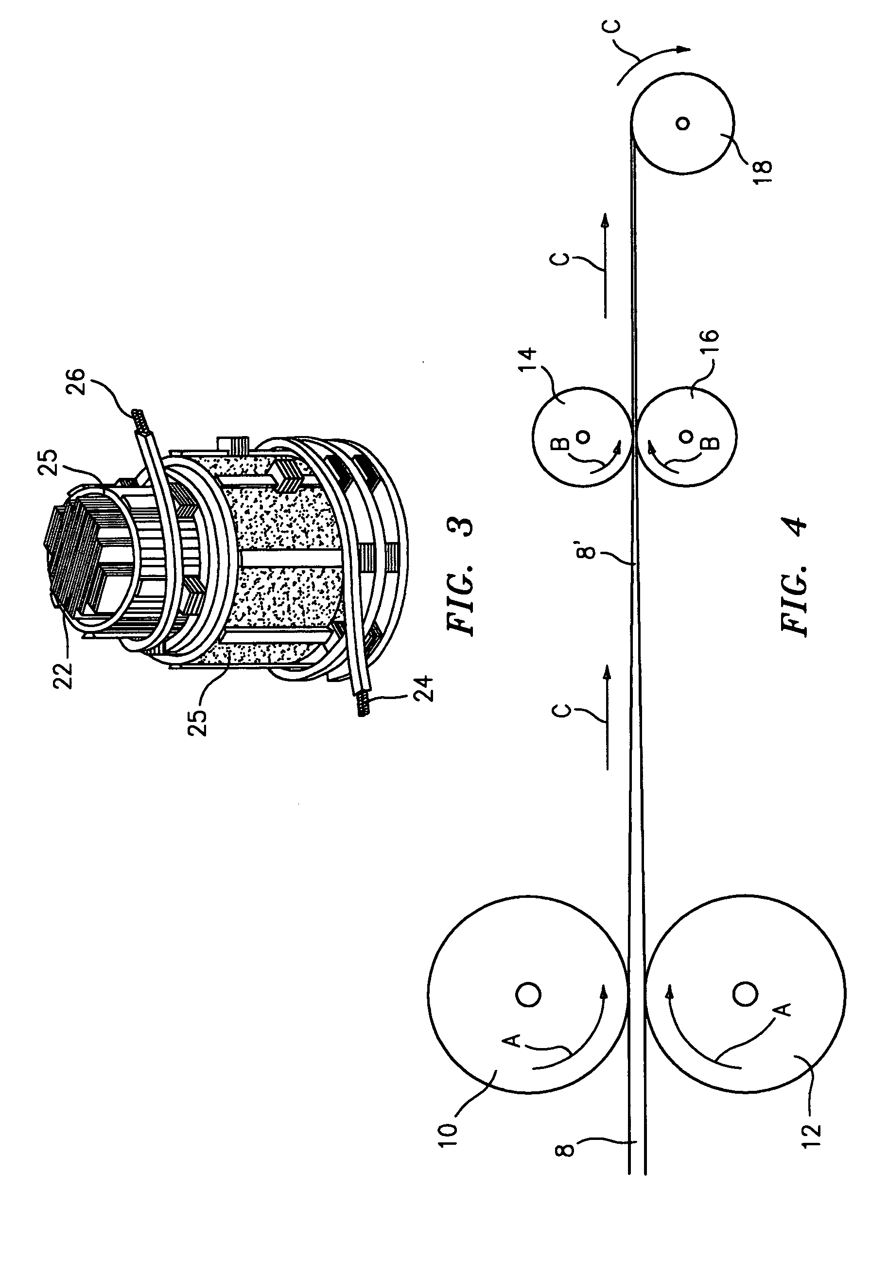
[0038]FIG. 3 is a fragmented perspective view of a transformer assembly which is suitable for use in an oil filled power system. The transformer assembly includes a core component 22, a low voltage winding coil 26 and a high voltage winding coil 24. The coils are formed from the insulated magnet wire 2 shown in FIGS. 1 and 2. Insulat...


PUM

PropertyMeasurementUnit
Fractionaaaaaaaaaa
Percent by massaaaaaaaaaa
Temperatureaaaaaaaaaa

Abstract

An aliphatic polyamide film or fibrous material is employed for electrical insulation in individual conductors, groups of conductors, magnet wire, magnet wire coils, and layers in liquid filled electrical transformers. The material is stabilized with additives that produce improved moisture resistance, moisture stability, thermal stability, thermal conductivity, reduced insulation thickness, reduced shrinkage, and improved insulation elasticity for the insulation material thereby providing a longer useful life for the material.

Description

CROSS REFERENCE TO RELATED APPLICATIONS[0001]This application claims the benefit of U.S. Ser. No. 61 / 189,198, filed Aug. 15, 2008 and U.S. Ser. No. 61 / 189,199, filed Aug. 15, 2008.TECHNICAL FIELD[0002]This invention relates to a thermoplastic film or fibrous material containing an aliphatic polyamide and / or one or more copolymers and / or additives thereof; to electrical components that are insulated by this material; and to the method of forming those components. More particularly, this invention relates to an aliphatic polyamide film or fibrous material for electrical insulation in individual conductors, groups of conductors, and layers in liquid filled electrical transformers, which material produces improved moisture resistance, moisture stability, thermal stability, thermal conductivity, reduced insulation thickness, reduced shrinkage, and improved insulation elasticity.BACKGROUND ART[0003]The current standard insulating materials in liquid filled transformers are cellulosic mate...

Claims


Application Information

Patent Timeline
IPC IPC(8): H01F27/12
CPCH01B3/305
Inventor WEINBERG, MARTIN
Owner WEINBERG MARTIN
Why Eureka
Try Eureka