
Systems and methods for microbial reductive dechlorination of environmental contaminants

a technology of environmental contaminants and microbial reductive dechlorination, which is applied in the field of bioremediation, can solve the problems of large dispersed plumes of chlorinated hydrocarbon solvents that are difficult and expensive to treat, small amounts of solvents can pose serious risks to the environment and water supply, and the current abiotic and biotic in situ remediation strategies available for groundwater contaminated with chlorinated dnapls have limitations and drawbacks, and achiev

Active Publication Date: 2010-03-11
UNIV OF MASSACHUSETTS +1
View PDF20 Cites 15 Cited by
  • Summary
  • Abstract
  • Description
  • Claims
  • Application Information

AI Technical Summary

Benefits of technology

[0014]In preferred embodiments, the present invention provides bioremediation systems for performing in situ bioremediation of one or more halogenated contaminants in a contaminated source zone. The bioremediation systems include an electrical power supply, an anodal source electrode, a cathodal counter electrode, and a microorganism biocatalyst comprising an electricigenic microbe that uses electrons from the source electrode to carry out a reductive dehalogenation of contaminant that is present in the soil, the groundwater, or both. The provided bioremediation systems advantageously have a continuous localized physical source of electrons, which is less likely to enhance undesired activity of competing microorganisms and does not add toxic residual compounds to a contaminated site.
[0026]In certain embodiments, the reductive dehalogenation of the contaminant facilitates dissolution of contaminant compounds into an aqueous phase in or near the contaminant source zone, thereby facilitating in situ bioremediation of non-aqueous halogenated solvent. In other embodiments, the method can be used in conjunction with a pump and treat method of removing chlorinated contaminants from groundwater at the contaminant source zone.

Problems solved by technology

Chlorinated hydrocarbon compounds, in particular, chlorinated hydrocarbon solvents, are prevalent contaminants of groundwater and aquatic sediments.
Even a small spill can result in large, dispersed plumes of chlorinated hydrocarbon solvents that are very difficult and expensive to treat.
Thus, even relatively small amounts of solvent can pose serious risks to the environment and to water supplies.
However, current abiotic and biotic in situ remediation strategies available for groundwater contaminated with chlorinated DNAPLs have limitations and drawbacks.
This method can be costly, depending on the site location and depth of the contaminated aquifer.
Such abiotic processes are limited by electrode material, temperature, ionic strength and pH of the groundwater, transportation of the target compound to the surface of the cathode, and the rate of charge transfer to the surface of the cathode.
Yet another limitation of reductive dechlorination in a source zone contaminated with chlorinated DNAPLs is intolerance of dechlorinating microorganisms to saturated concentrations of chlorinated substrate, commonly found at source zones.
However, these approaches are not appropriate for in situ treatment of chlorinated contaminants in aquifers or in aquatic sediments.
However, these approaches have significant limitations for in situ treatment of groundwater or soil because: 1) hydrogen gas is produced, which can stimulate the growth of anaerobic microorganisms resulting in the accumulation of unwanted biomass and production of undesirable end-products, such as Fe(II), sulfide, and methane that deteriorate water quality; 2) reduction of protons results in high groundwater pH which disrupts biological, chemical, and physical properties of the soil; and 3) non-specific reduction of protons, and possibly other groundwater constituents, results in poor efficiency in electron transfer to the chlorinated contaminants of interest.
However, methylviologen (1,1′-dimethyl-4,4′-bipyridinium dichloride, also known as paraquat dichloride) itself is highly toxic and thus is considered a contaminant.
Appropriate addition of a chemical electron donor without unduly stimulating growth of unwanted non-dechlorinating microorganisms, or inhibiting growth of beneficial dechlorinating microorganisms can be particularly challenging.

Method used


Image

  • Systems and methods for microbial reductive dechlorination of environmental contaminants
  • Systems and methods for microbial reductive dechlorination of environmental contaminants
  • Systems and methods for microbial reductive dechlorination of environmental contaminants

Examples


example 1

G. Lovleyi is Capable of Accepting Electrons Directly from a Source Electrode

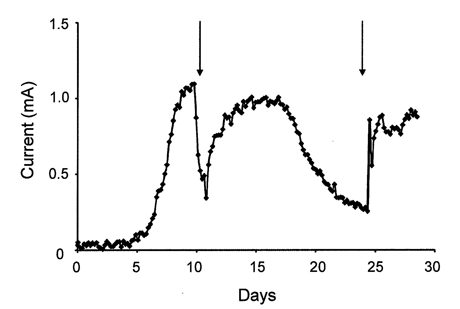
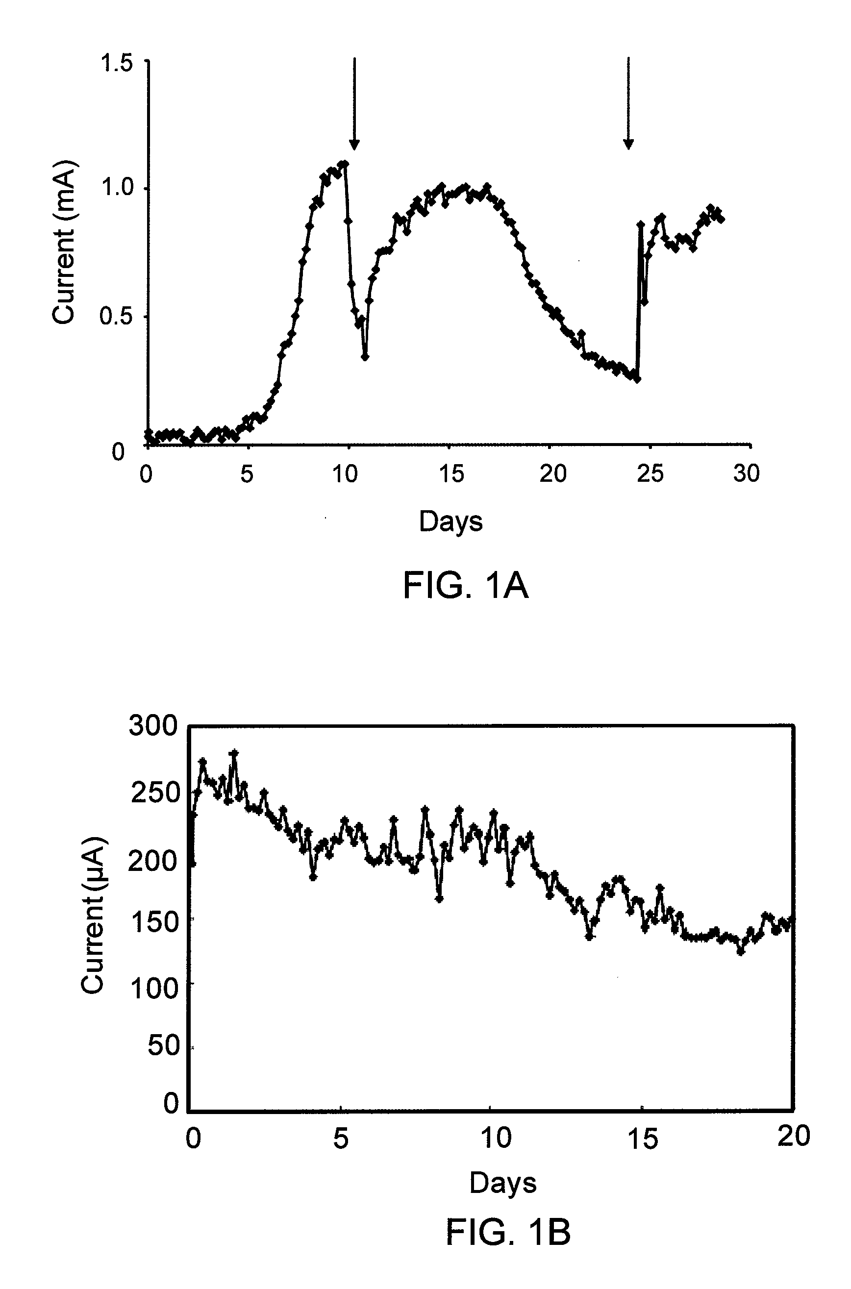
[0090]FIG. 1 is a graph showing the current production by G. lovleyi with acetate (10 mM) serving as the electron donor and a poised electrode serving as the electron acceptor. The arrows indicate when fresh acetate medium was added. The data are from a representative example of duplicate current producing cultures.

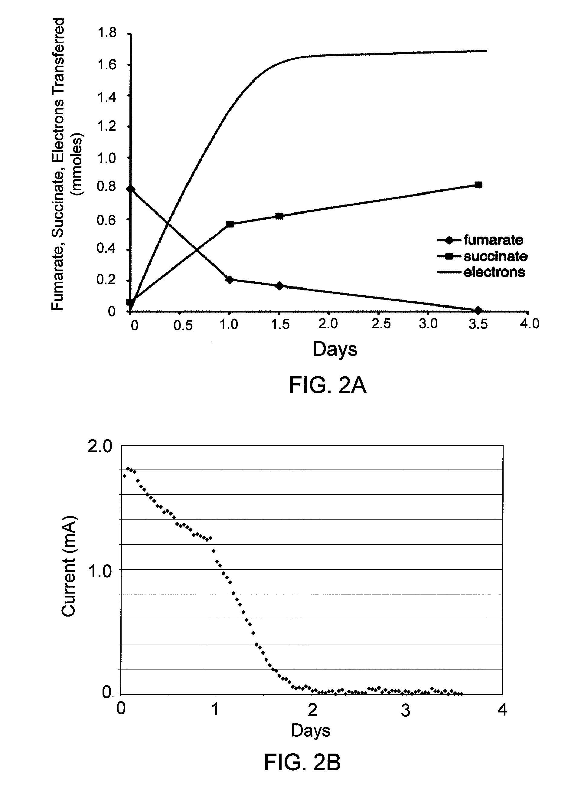
[0091]In order to determine whether G. lovleyi could also accept electrons from an electrode, studies similar to that previously described with G. sulfurreducens in which an electrode served as the electron donor and fumarate as the electron acceptor were performed. FIG. 2A and FIG. 2B are graphs showing the reduction of fumarate by G. lovleyi, and use of electrons from a graphite electrode as electron donor. After current transfer from the electrode was established with fumarate (20 mM) and low levels of acetate (2 mM), growth media was replaced with fresh media containing fumarate (0.8 mmoles) ...

example 2

G. Lovleyi does Reductive Dechlorination Using Electrons Directly from a Source Electrode

[0094]In order to determine if reductive dechlorination was possible with an electrode serving as the electron donor, G. lovleyi was again grown in the presence of a poised electrode, but with acetate (2 mM) and PCE (39 μmoles) as the electron acceptor. The amount of PCE that can be added is much lower than the amount of fumarate, due to toxicity of PCE to the strain at high concentrations. Once reduction of PCE to cis-dichloroethene (cis-DCE) was observed, the medium was replaced with a new medium containing PCE (39 μmoles) as the electron acceptor, but with the electrode serving as the sole electron donor. Lactate (2 mM), which does not serve as an electron donor for G. lovleyi (Sung et al., 2006), was added as a carbon source. Once PCE was completely reduced to cis-DCE with the electrode serving as the electron donor, additional feedings of 39 μmoles were repeated until maximum rates of dechl...

example 3

A. Dehalogenans Reductive Dechlorination Using Electrons Directly from a Source Electrode

[0097]Chlorinated aromatic compounds are another important class of chlorinated contaminants. Anaeromyxobacter dehalogenans species are capable of dehalogenating 2-chlorophenol. Like the Geobacter species, to which they are related, they are also capable of extracellular electron transfer to Fe(III). A. dehalogenans strain 2CP-1 produced current with acetate as the electron donor. FIG. 1B is a graph showing the current production by A. dehalogenans strain 2CP-1 with acetate as the electron donor and poised graphite electrode (+500 mV vs. SHE). Cultures of A. dehalogenans were grown at room temperature (ca. 22-25°under N2:CO2 (80:20) in 200 ml of stirred (180 rpm) medium in the 265 ml working electrode (anode) chamber of an anaerobic, dual-chambered electrode system. Acetate (10 mM) was provided as the electron donor, and initially, both fumarate (40 mM) and the electrode (+300 mV vs. SHE) were a...


PUM

PropertyMeasurementUnit
electrode potentialaaaaaaaaaa
angleaaaaaaaaaa
angleaaaaaaaaaa

Abstract

In preferred embodiments, bioremediation systems are provided that comprise electricigenic microbes that use electrons provided directly from the anode of an electrical bioremediation system to carry out reductive dehalogenation of halogenated hydrocarbon contaminants, including chlorinated solvents. The present invention also provides methods of performing in situ bioremediation of halogenated solvents in groundwater or soil through the use of the provided systems.

Description

RELATED APPLICATION[0001]This application claims benefit of U.S. Provisional Patent Application 61 / 087,450, filed Aug. 8, 2008, the entire contents of which are incorporated by reference for all purposes.STATEMENT REGARDING FEDERALLY SPONSORED RESEARCH[0002]Research carried out in connection with this invention was supported in part by the Office of Naval Research grant OGCA-1070875. Accordingly, the United States government may have certain rights in the invention.FIELD OF THE INVENTION[0003]The present invention relates generally to bioremediation. Specific embodiments relate to compositions and methods for bioremediation of chlorinated hydrocarbons by microorganisms, including a bioremediation system using a powered source electrode and a microorganism capable of reductive dechlorination and capable of utilizing electrons directly from the source electrode for electron transfer and reduction of contaminants.BACKGROUND OF THE INVENTION[0004]Chlorinated hydrocarbon compounds, in pa...

Claims


Application Information

Patent Timeline
Patent Type & Authority Applications(United States)
IPC IPC(8): C02F3/00B09C1/00
CPCB09C1/10B09C1/085
Inventor LOVLEY, DEREK R.STRYCHARZ, SARAHLOEFFLER, FRANK
Owner UNIV OF MASSACHUSETTS
Learn More