Optical microscope

a microscope and optical technology, applied in the field of optical microscopes, can solve the problems of inability to use conventional fluorescent microscopes, inability to respond to fluorescence, etc., and achieve the effect of good s/n ratio

Inactive Publication Date: 2010-03-18
OLYMPUS CORP
View PDF7 Cites 39 Cited by
  • Summary
  • Abstract
  • Description
  • Claims
  • Application Information

AI Technical Summary

Benefits of technology

[0057]According to the present invention, stimulation light and erase light having a wavelength different from that of the stimulation light simultaneously are irradiated on the sample such that response light emitted from a light-collecting area of the stimulation light is not suppressed but

Problems solved by technology

Further, since the responsive amount of fluorescence is proportional to square of irradiation intensity, a fluorescence responsive region is limited in a very small region in a three-dimensional space.
In a case wh

Method used


Image

  • Optical microscope
  • Optical microscope
  • Optical microscope

Examples


first embodiment

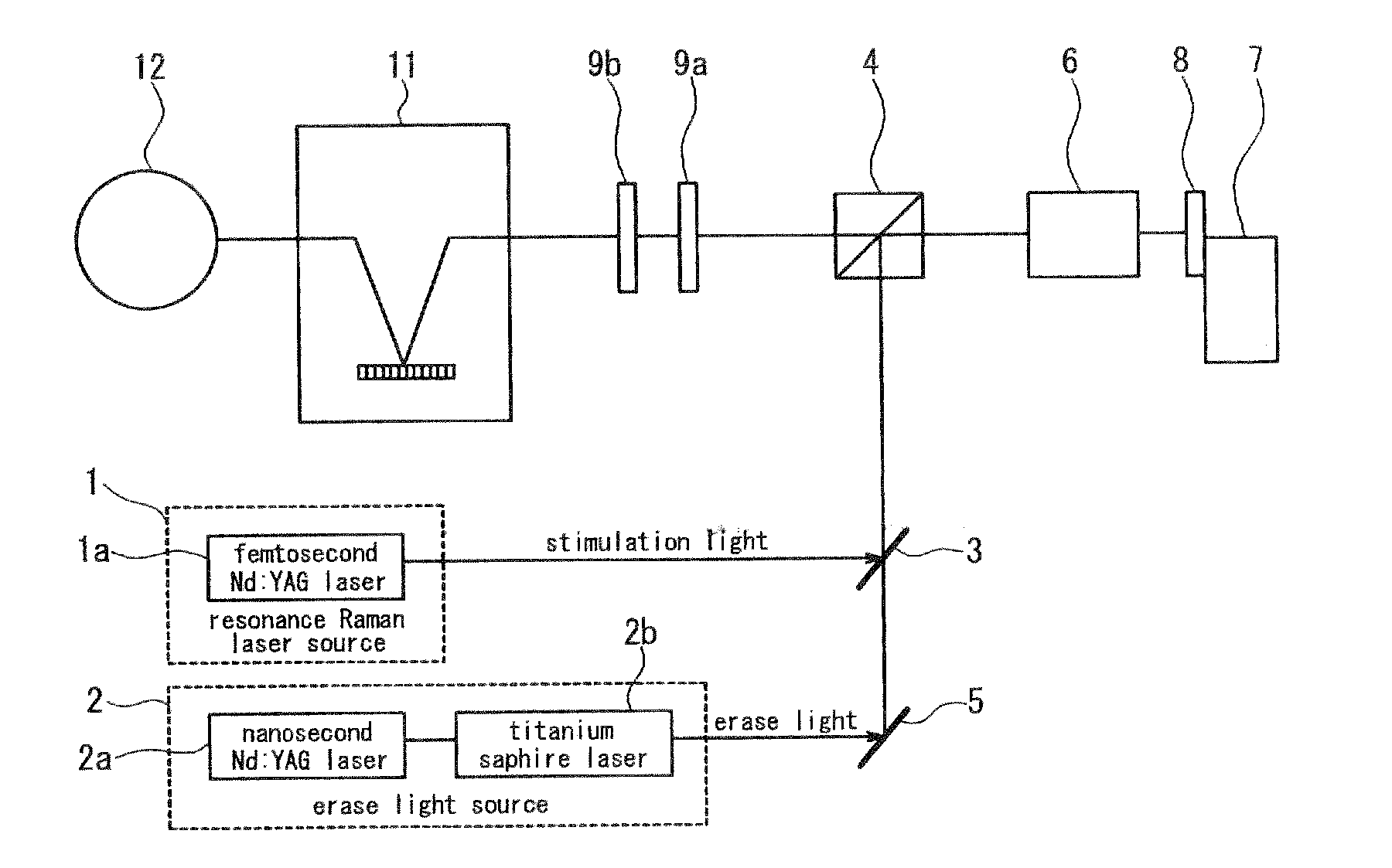
[0098]A microscope according to the first embodiment of the present invention visualizes a biological molecule by using resonance Raman scattering. The Biological sample includes, for example, nucleobase such as tryptophan, tyrosine, phenylalanine and adenine. Such nucleobase, which is an important molecule to analyze living structure and activity thereof, includes a benzene ring and a nitrogen base and has a S0 →S1 absorption band by extremely strong electronic transition in a wavelength band around 260 nm. Thus, if these molecules are exited by fourth-harmonic wave of Nd:YAG laser light (wavelength 266 nm) as Raman process-inducing stimulation light, Raman band can be made to appear in a wavelength band of 290 nm to 400 nm.

[0099]However, the above-mentioned molecules have a strong fluorescence band around the wavelength of 360 nm. Therefore, in conventional resonance Raman scattering microscopy using only Raman process-inducing stimulation light, a fluorescence band becomes a back...

second embodiment

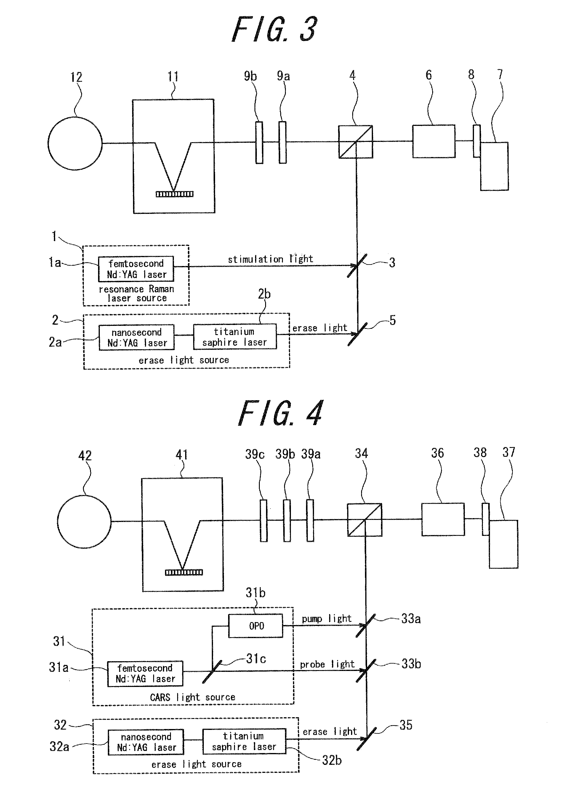
[0107]Environmentally responsive fluoroprobe of a biological sample is observed with a microscope according to a second embodiment of the present invention, by utilizing coherent Raman scattering. In a coherent Raman microscope, staining a biological sample is not generally required because resonance oscillation of a molecule is converted to signals. However, when environmentally responsive fluoroprobe is observed with a conventional coherent Raman microscope, a two-photon absorption process and the like may follow and there is a possibility that a Raman signal is buried among fluorescence signals and cannot be detected.

[0108]By the way, when an environmentally responsive fluoroprobe takes in or absorbs a particular molecule, atom or ion, it greatly increases a fluorescence yield and emits intense fluorescence. Further, a fluorescence yield greatly varies depending on ambient temperature and pressure so that the environmentally responsive fluoroprobe is either fluorescent or non-flu...

third embodiment

[0120]A sample stained by a fluorescent dye in a two-photon absorption process is observed with a microscope according to a third embodiment of the present invention. FIG. 5 is a schematic block diagram of a main part of a two-photon microscope according to the present embodiment. This two-photon microscope has a two-photon excitation light source 51 which is a stimulation light source and an erase light source 52. The two-photon excitation light source 51 uses, for example, a titanium sapphire pulsed laser of mode lock type and generates, from the titanium sapphire pulsed laser, pulsed light having relatively high peak power and a pulse width of not more than 10 picoseconds in a relatively wide wavelength range from 900 nm (near-infrared) to 700 nm as pump light (stimulation light). The pump light of this wavelength range excites fluorescent dye having rhodamine, fluoroscein and the like in the molecular skeleton thereof to make the dye generate fluorescence.

[0121]The erase light s...


PUM


Abstract

The present invention provides an optical microscope capable of suppressing unnecessary response light as a background and detecting desired response light in nonlinear optical response process with a good S/N ratio. The optical microscope for collecting, on a sample 8, stimulation light emitted from a stimulation light source 1 and having a single wavelength or a plurality of different wavelengths, and detecting response light emitted from the sample 8 in nonlinear optical response process, comprises: an erase light source 2 for emitting erase light having a wavelength different from that of the stimulation light and inducing an effect of suppressing secondary response light which appears due to irradiation of the stimulation light on the sample 8, wherein the erase light and the stimulation light are simultaneously irradiated on the sample 8 such that the erase light does not suppress response light emitted from a light-collecting area of the stimulation light but suppresses the secondary response light other than the response light emitted from a light-collecting area of the stimulation light.

Description

CROSS-REFERENCE OF RELATED APPLICATION[0001]The present application claims the priorities of Japanese Patent Application No. 2008-234,738 filed on Sep. 12, 2008 and Japanese Patent Application 2009-068,854 filed on Mar. 19, 2009, which are herein incorporated in the entirety thereof for reference.BACKGROUND OF THE INVENTION[0002]1. Field of the Invention[0003]The present invention relates to an optical microscope for observing a sample by using nonlinear optical response process.[0004]2. Description of the Related Art[0005]The technique of optical microscopes has a long history, during which various types of optical microscopes have been developed. In recent years, as a result of progress in the peripheral technologies such as laser technology and electronic imaging technology, high-performance optical microscope systems have been developed.[0006]In such a background, high-performance optical microscopes using various spectral processes have been proposed, so that not only a shape o...

Claims


Application Information

Patent Timeline
IPC IPC(8): G02B21/06
CPCG01N21/636G01N21/6458G02B21/16G01N2021/1736G01N2021/6493G01N21/65
Inventor YOKOI, EIJIIKETAKI, YOSHINORI
Owner OLYMPUS CORP
Why Eureka
Try Eureka