

Process for producing isocyanates
- Summary
- Abstract
- Description
- Claims
- Application Information
AI Technical Summary
Benefits of technology
Problems solved by technology
Method used
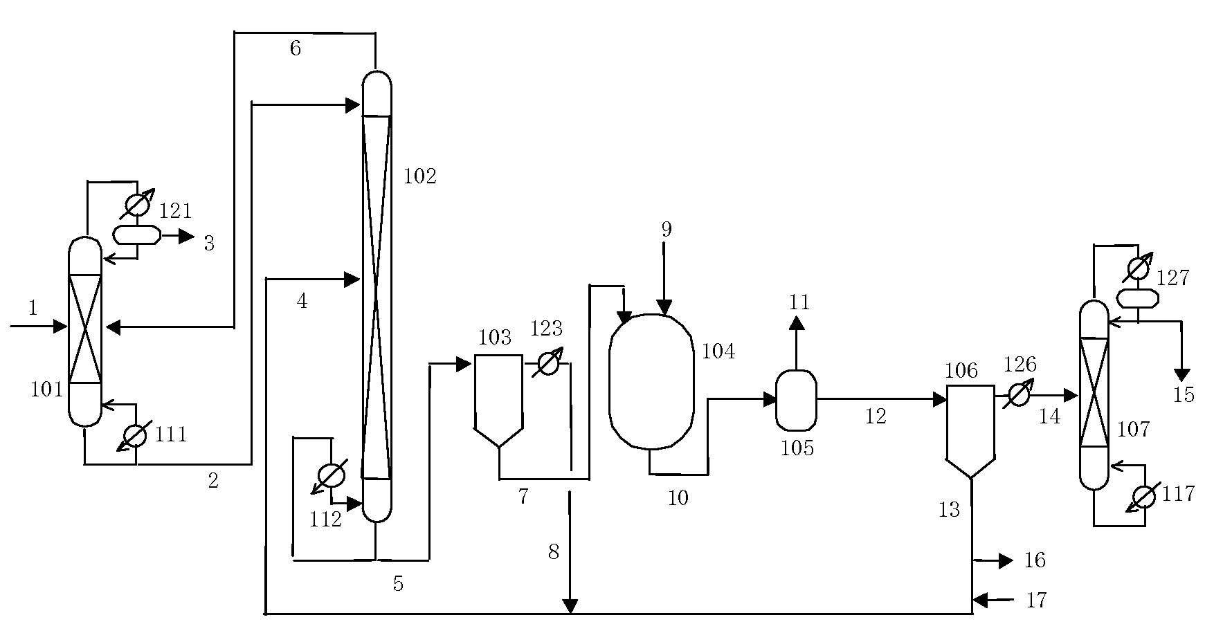
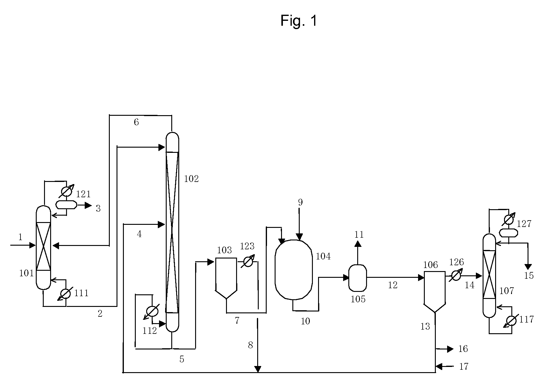
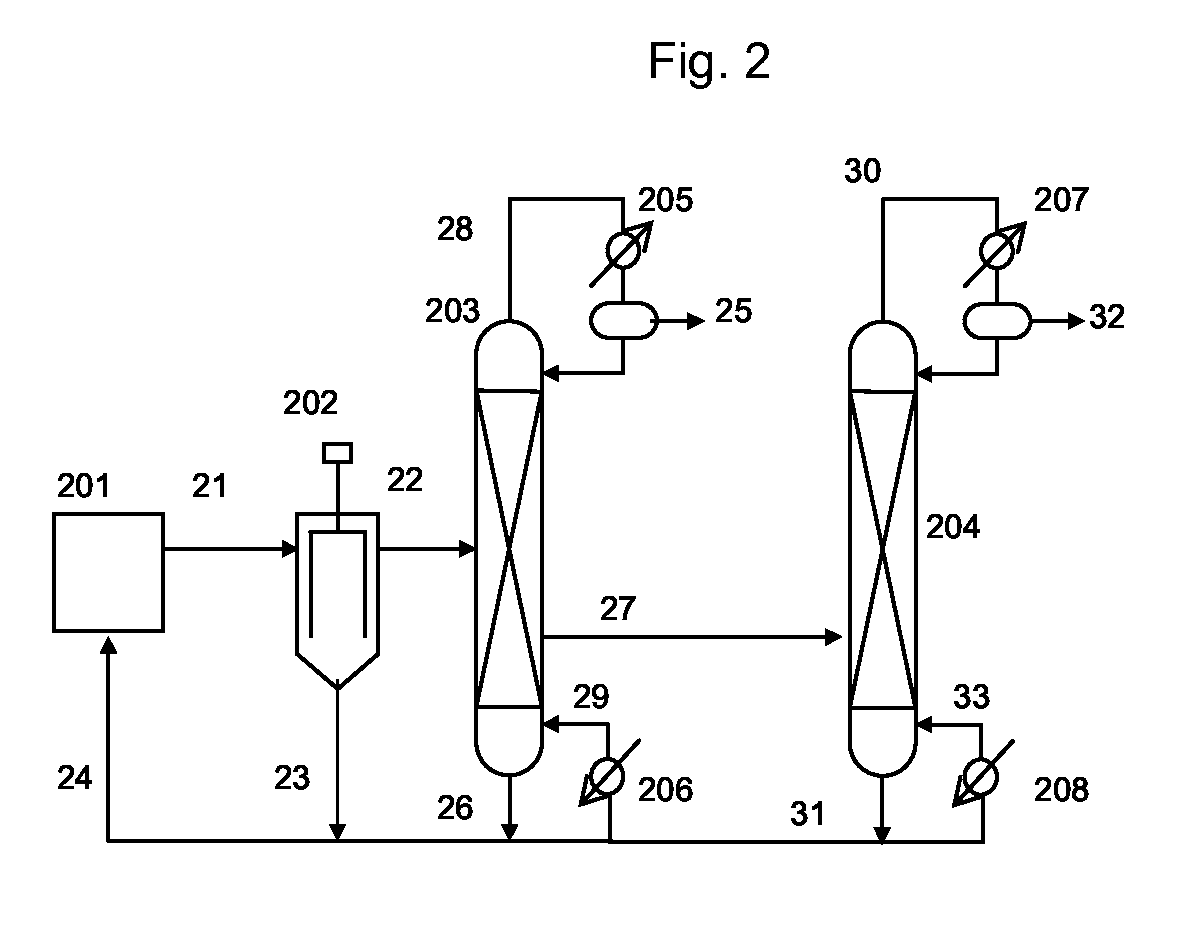
Image

Examples
reference example 1
Production of Bis(3-methylbutyl) Carbonate
[0162]Step (I-1): Production of Dialkyl Tin Catalyst
[0163]625 g (2.7 mol) of di-n-butyl tin oxide (Sankyo Organic Chemicals Co., Ltd., Japan) and 2020 g (22.7 mol) of 3-methyl-1-butanol (Kuraray Co., Ltd., Japan) were placed in a 5000 mL volumetric pear-shaped flask. The flask was connected to an evaporator (R-144, Shibata Co., Ltd., Japan) to which was connected an oil bath (OBH-24, Masuda Corp., Japan) equipped with a temperature controller, a vacuum pump (G-50A, Ulvac Inc., Japan) and a vacuum controller (VC-10S, Okano Seisakusho Co., Ltd.). The purge valve outlet of this evaporator was connected to a line containing nitrogen gas flowing at normal pressure. After closing the purge valve of the evaporator to reduce pressure inside the system, the purge valve was opened gradually to allow nitrogen to flow into the system and return to normal pressure. The oil bath temperature was set to about 145° C., the flask was immersed in the oil bath ...
reference example 2
Production of Dibutyl Carbonate
[0166]Step (II-1): Production of Dialkyl Tin Catalyst
[0167]692 g (2.78 mol) of di-n-butyl tin oxide and 2000 g (27 mol) of 1-butanol (Wako Pure Chemical Industries, Ltd., Japan) were placed in a 3000 mL volumetric pear-shaped flask. The flask containing the white, slurry-like mixture was attached to an evaporator to which was connected an oil bath equipped with a temperature controller, a vacuum pump and a vacuum controller. The purge valve outlet of this evaporator was connected to a line containing nitrogen gas flowing at normal pressure. After closing the purge valve of the evaporator and reducing pressure inside the system, the purge valve was opened gradually to allow nitrogen to flow into the system and return to normal pressure. The oil bath temperature was set to about 126° C., the flask was immersed in the oil bath and rotation of the evaporator was started. After rotating, stirring and heating for about 30 minutes at normal pressure with the ...
example 1
Step (1-1): Production of N,N′-hexanediyl-bis-carbamic Acid Bis(3-methylbutyl) Ester
[0170]2121 g (10.5 mol) of bis(3-methylbutyl) carbonate and 243.6 g (2.1 mol) of hexamethylene diamine (Aldrich Corp., USA) were placed in a 5 L volumetric four-mouth flask, a stirrer was placed in the flask, and a Dimroth condenser and a three-way valve were attached to the flask. After replacing the inside of the system with nitrogen, the four-mouth flask was immersed in an oil bath (OBH-24, Masuda Corp., Japan) heated to 80° C. followed by the addition of 40.5 g of sodium methoxide (28% methanol solution, Wako Pure Chemical Industries, Ltd., Japan) to start the reaction. Samples of the reaction liquid were suitably collected and subjected to NMR analysis, and the reaction was terminated at the time when hexamethylene diamine was no longer detected. As a result of analyzing the resulting solution by liquid chromatography, the solution was found to contain 29.9% by weight of N,N′-hexanediyl-bis-carb...
PUM
| Property | Measurement | Unit |
|---|---|---|
| Structure | aaaaa | aaaaa |
| Boiling point | aaaaa | aaaaa |
Abstract
Description
Claims
Application Information