Honeycomb structure and method for manufacturing the same

a technology of honeycomb and structure, applied in the field of honeycomb structure, can solve the problems of increasing pressure loss, reducing the purification efficiency of the honeycomb catalyst body, and not solving the problem, so as to increase the average increase the pore size of the honeycomb structure, and increase the porosity of the partition walls

Active Publication Date: 2010-04-08
NGK INSULATORS LTD
View PDF10 Cites 22 Cited by
  • Summary
  • Abstract
  • Description
  • Claims
  • Application Information

AI Technical Summary

Benefits of technology

[0021]In a honeycomb structure of the present invention, the average pore size of the honeycomb structure can be increased even without using a raw material powder having a large particle size or a pore former having a large particle size. Specifically, upon the cordierite-forming reaction of the cordierite-forming raw material, the sodium components accelerate the liquid phase reaction to increase the average pore size of the honeycomb structure.
[0022]In addition, in a honeycomb structure of the present invention, the porosity of the partition walls can be increased. Further, as described above, since the average pore size can be increased even without using a raw material powder having a large particle size or a pore former having a large particle size, the slits in the die for extrusion-forming of kneaded clay are hardly clogged, and therefore, thinning of the partition walls can be realized while increasing the average pore size.
[0023]In the method for manufacturing a honeycomb structure of the present invention, since a formed article can be obtained by the use of kneaded clay made of a raw material powder having a relatively small particle size, the slits in the die for forming are hardly clogged, which enables high-yield manufacture of a honeycomb structure having a large average pore size.

Problems solved by technology

However, since pressure loss also increases inversely with the square of cell hydraulic diameter, there arises a problem of increase in pressure loss in accordance with the rise in transmission rate of the target components to be purified.
In addition, in the case that diffusion speed of the target components to be purified is insufficient in the catalyst layer, purification efficiency tends to decrease in the honeycomb catalyst body.
However, such a method does not solve the problem of the increase in pressure loss.
However, in the case that a honeycomb catalyst body is large, a problem of difficulty in mounting the honeycomb catalyst body on an automobile remains since the space for mounting is limited.

Method used


Image

  • Honeycomb structure and method for manufacturing the same
  • Honeycomb structure and method for manufacturing the same
  • Honeycomb structure and method for manufacturing the same

Examples


example 1

[0087]As an alumina source, 30 parts by mass of alumina (referred to as “alumina 1” in Table 1) having a particle size of 20 μm and containing sodium at 0.4 mass % in terms of sodium oxide, 43 parts by mass of talc having a particle size of 30 μm and containing sodium at 0.01 mass % in terms of sodium oxide, and 22 parts by mass of silica having a particle size of 30 μm were mixed together to prepare a cordierite-forming raw material (100 parts by mass in total). Incidentally, in Table 1, the rate of sodium in each component in terms of sodium oxide is shown as “Na2O amount (mass %)”.

[0088]Next, to 100 parts by mass of the cordierite-forming raw material were added 6 parts by mass of acrylic water-absorbing resin having a particle size of 40 μm and 70 parts by mass of water, and they were mixed to obtain a ceramic raw material, which was then kneaded to obtain kneaded clay having plasticity.

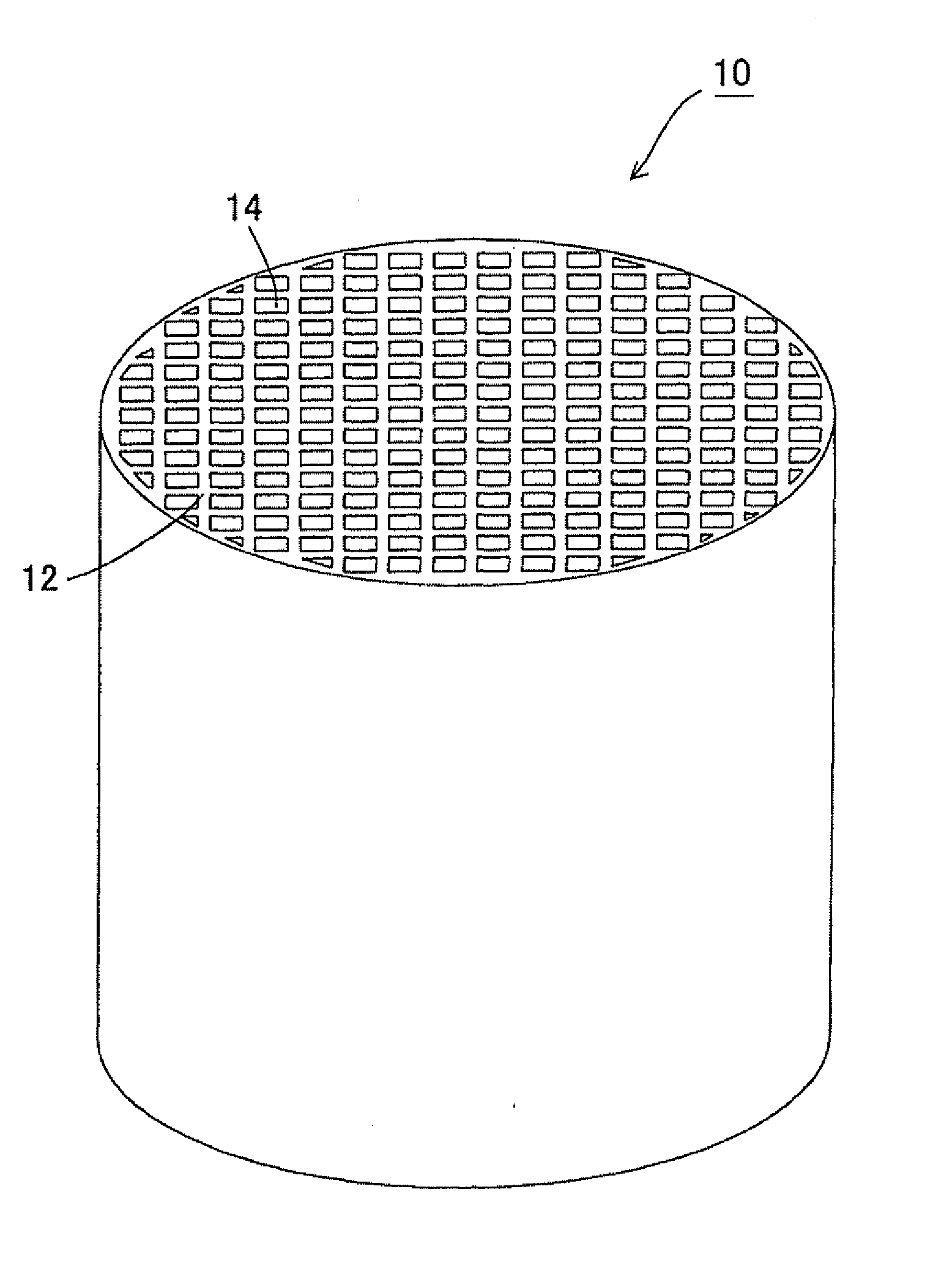
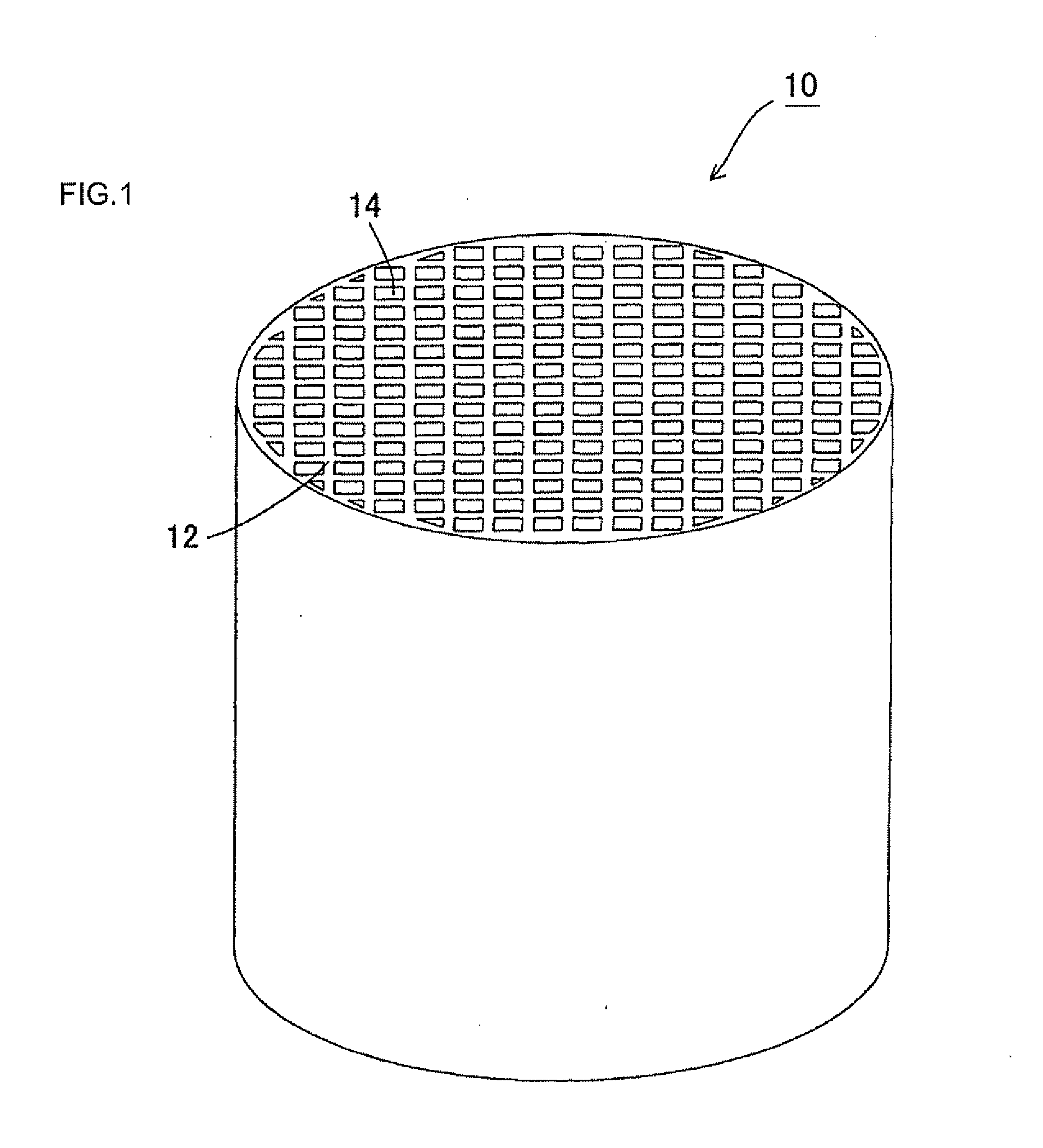
[0089]Next, the kneaded clay was formed into a cylindrical shape by a vacuum kneader and then...

examples 2 to 15

Comparative Examples 1 to 3

[0092]Honeycomb structures were obtained in the same manner as in Example 1 except that the blending formulation of the ceramic raw material was changed as shown in Tables 1 and 2. Each of the honeycomb structures was subjected to the measurements and the evaluation in the same manner as in Example 1. The results are shown in Tables 1 and 2. Incidentally, since the honeycomb structure in Comparative Example 3 melted upon firing, the measurements could not be performed except for the evaluation of the formed condition.

TABLE 2Example 10Example 11Example 12Example 13MaterialAlumina 1Amount (parts by mass)29151035Particle size (μm)20202020Na2O amount (mass %)0.40.71.00.4Alumina 2Amount (parts by mass)—2025—Particle size (μm)—2020—Na2O amount (mass %)—0.10.1—TalcAmount (parts by mass)42434343Particle size (μm)30303030Na2O amount (mass %)0.020.010.010.01SilicaAmount (parts by mass)17222222Particle size (μm)30303030Na2O amount (mass %)0000KaolinAmount (parts by m...


PUM

PropertyMeasurementUnit
thicknessaaaaaaaaaa
pore sizeaaaaaaaaaa
porosityaaaaaaaaaa

Abstract

A honeycomb structure 10 of the present invention is provided with porous partition walls 12 made of a ceramic material containing cordierite as a main crystal phase and separating and forming a plurality of cells 14 functioning as fluid passages. The partition walls 12 contain sodium at 0.08 to 0.15 mass % in terms of sodium oxide. A honeycomb structure having a large average pore size can be provided.

Description

BACKGROUND OF THE INVENTION AND RELATED ART STATEMENT[0001]The present invention relates to a honeycomb structure and a method for manufacturing the honeycomb structure. More specifically, the present invention relates to a honeycomb structure capable of serving as a honeycomb catalyst body used for purifying target components to be purified contained in exhaust gas discharged from an engine and the like of an automobile by loading a catalyst.[0002]In various kinds of fields such as chemistry, electric power, iron and steel, a ceramic honeycomb structure excellent in thermal resistance and corrosion resistance is employed as a carrier for a catalyst apparatus used for an environmental measure or collection of specific substances or a filter (see, for example, JP-A-2003-33664).[0003]For example, in order to purify exhaust gas discharged from various kinds of engines and the like, there is used a catalyst body (hereinbelow sometimes referred to as a “honeycomb catalyst body”) obtained...

Claims


Application Information

Patent Timeline
Patent Type & Authority Applications(United States)
IPC IPC(8): B32B3/12C04B33/00
CPCB01J35/04C04B35/195C04B38/0009C04B2111/00793C04B2111/0081Y10T428/24149C04B2235/5436F01N3/2828C04B2235/3201
Inventor NOGUCHI, YASUSHINAKANE, YUKARI
Owner NGK INSULATORS LTD
Why Eureka
Try Eureka