

Front end of line plasma mediated ashing processes and apparatus
a plasma mediated shing and plasma technology, applied in the direction of electrical equipment, basic electric elements, electric discharge tubes, etc., can solve the problems of affecting device performance, yield, reliability of the final integrated circuit, adversely affecting the performance of the device, and altering the electrical functioning of the device, so as to achieve the effect of enhancing the formation of active nitrogen
- Summary
- Abstract
- Description
- Claims
- Application Information
AI Technical Summary
Benefits of technology
Problems solved by technology
Method used
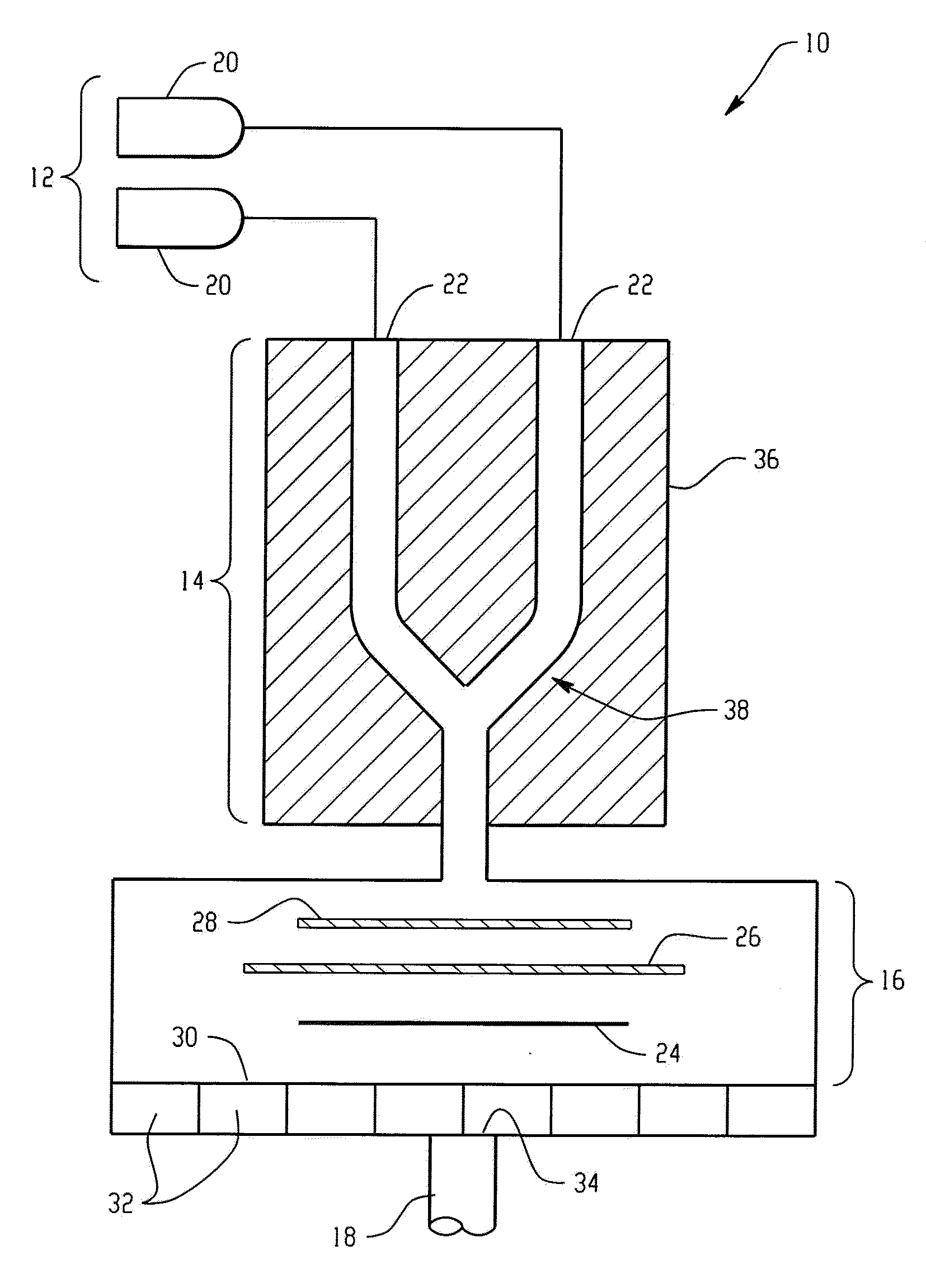
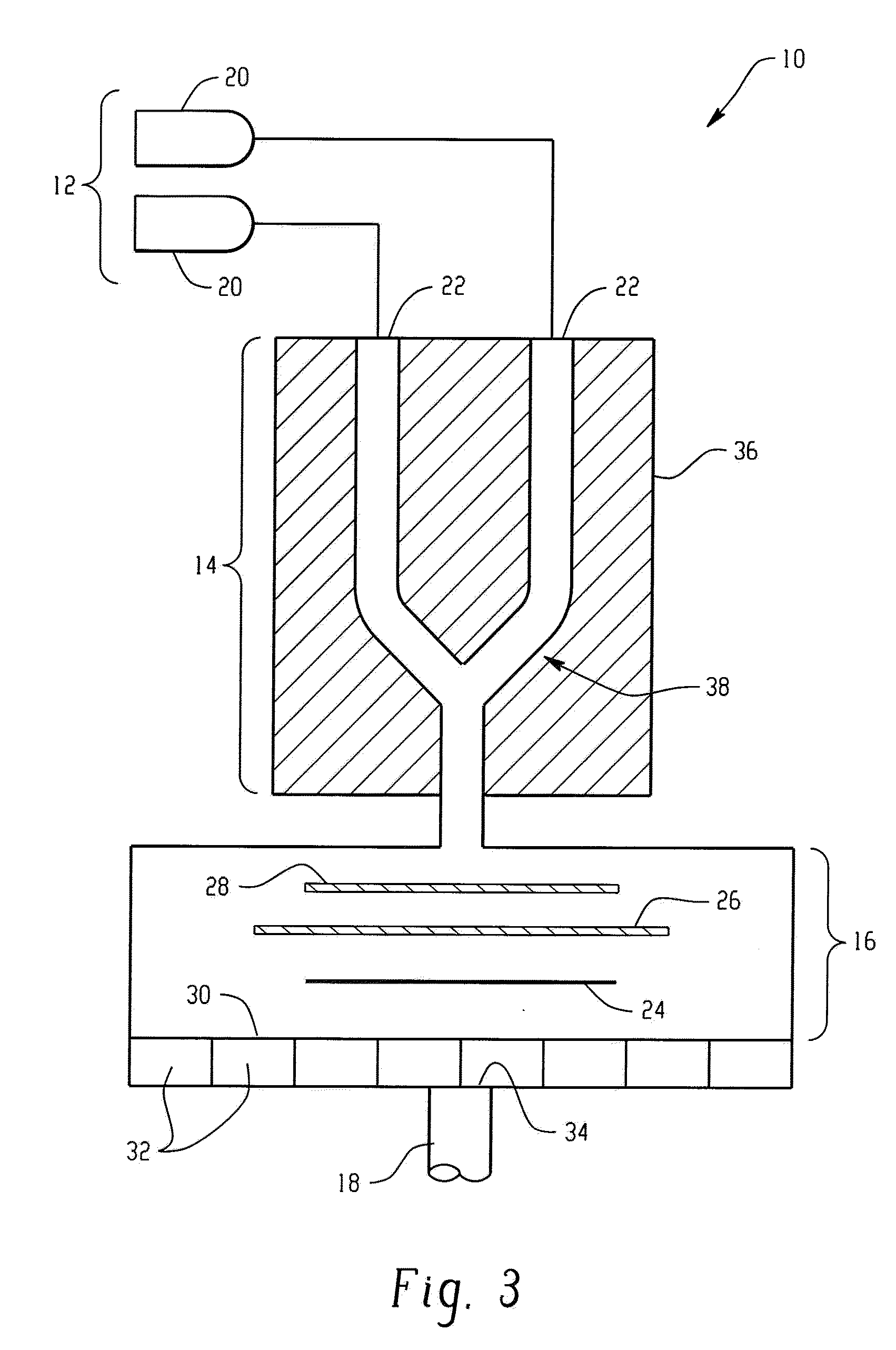
Image

Examples
example 1
[0056]In this example, photoresist coated onto a silicon substrate was exposed to a nitrous oxide stripping chemistry in a RapidStrip320 plasma ashing tool commercially available from Axcelis Technologies, Inc. The photoresist was an i-line photoresist commercially available from Fuji Company under the tradename 10i and was deposited onto the silicon substrate at a thickness of 1.9 microns. The plasma chemistry was formed by flowing nitrous oxide gas at 7 standard liters per minute (slm) into the plasma ashing tool at a pressure of 1 Torr, a temperature of 240° C., and a power setting of 3500 Watts.
[0057]Ashing rate, cross wafer uniformity, and oxide growth of the nitrous oxide plasma stripping process was compared with oxygen-free reducing plasma (forming gas) and an oxygen based plasma. The reducing plasma was formed from a gas mixture of forming gas (3% hydrogen in nitrogen) at a flow rate of 7 slm into the plasma ashing tool at a pressure of 1 Torr, a temperature of 240° C. and ...
example 2
[0060]In this example, a small amount of CF4 was added to different plasma gas mixtures and processed in the RapidStrip320 plasma ashing tool. Silicon substrates were exposed to the different plasma chemistries and oxide growth was measured. The results are shown in Table 1 below. In each instance, the various plasmas were formed using a flow rate of the gas mixture of 7 slm into the plasma ashing tool at a pressure of 1 Torr, and a power setting of 3500 Watts. As indicated in the Table, the amount of CF4 trickled into the plasma ashing tool, where indicated, was 20 standard cubic centimeters per minute (sccm).
TABLE 1Plasma ChemistryProcess TimeOxide Growth (Å)CF4 / N2O1033.24CF4 / 3% O2 / Forming Gas1039.54CF4 / 90% O2 / Forming Gas1038.763% O2 / Forming Gas1409.82
[0061]As shown, trickling CF4 during formation of the plasma resulted in minimal substrate loss as evidenced by the oxide growth, and advantageously, can be expected to produce more energetic species, which should effectively increas...
example 3
[0062]In this example, substrate damage was measured using the RapidStrip320 plasma ashing tool in terms of silicon loss, oxide growth and oxide loss for a plasma formed from nitrous oxide, which was compared to prior art plasmas formed from O2 / forming gas mixtures with and without a small amount of carbon tetrafluoride. The forming gas composition was 3% hydrogen in nitrogen. The results are graphically shown in FIG. 5A. In each instance, the various plasmas were formed using a flow rate of the gas mixture of 7 slm into the plasma ashing tool at a pressure of 1 Torr, a temperature of 240° C. and a power setting of 3500 Watts. The amount of CF4 trickled into the plasma ashing tool, where indicated, was 20 standard cubic centimeters per minute (sccm). The substrate damage included (i) silicon loss from silicon-on-insulator (SOI) test structures, (ii) silicon-oxide growth on bare silicon test wafers and silicon-oxide loss from silicon thermal oxide test wafers. Panels (b) and (c) comp...
PUM
| Property | Measurement | Unit |
|---|---|---|
| Pressure | aaaaa | aaaaa |
| Ratio | aaaaa | aaaaa |
| Energy | aaaaa | aaaaa |
Abstract
Description
Claims
Application Information