Method of producing magnetic recording medium, and magnetic recording and reading device

Active Publication Date: 2010-07-01
SHOWA DENKO KK
View PDF14 Cites 18 Cited by
  • Summary
  • Abstract
  • Description
  • Claims
  • Application Information

AI Technical Summary

Benefits of technology

[0042]According to the present invention, a magnetic recording medium which has excellent magnetic recording pattern-separating properties and excellent high recording-density properties, and which is unlikely influenced by the signal interference between adjacent patterns can be produced at a high production rate with regard to the magnetic recording medium wherein the magnetic recording pattern is formed after the magnetic layer is formed over the non-magnetic substrate.
[0043]Because the magn

Problems solved by technology

However, as the track density is increased, magnetically-recorded data will interfere with each other between adjacent tracks.
Consequently, the magnetic transition region of the boundary portion will be a noise source, and it is likely to impair the SNR.
This leads to a increase of the bit error rate, and such a problem is an obstacle to improving the recording density.
However, as the recording bit is made smaller, the magnetic minimum volume per bit will be small, and there is a problem in which recorded data disappear due to the flux reversal caused from heat fluctuation.
However, it is difficult to attain sufficient reading output in the method, and there is a problem in which it is difficult to obtain a sufficient SNR.
The technique has a disadvantage in which the medium is likely to be contaminated during

Method used


Image

  • Method of producing magnetic recording medium, and magnetic recording and reading device
  • Method of producing magnetic recording medium, and magnetic recording and reading device
  • Method of producing magnetic recording medium, and magnetic recording and reading device

Examples


example 1

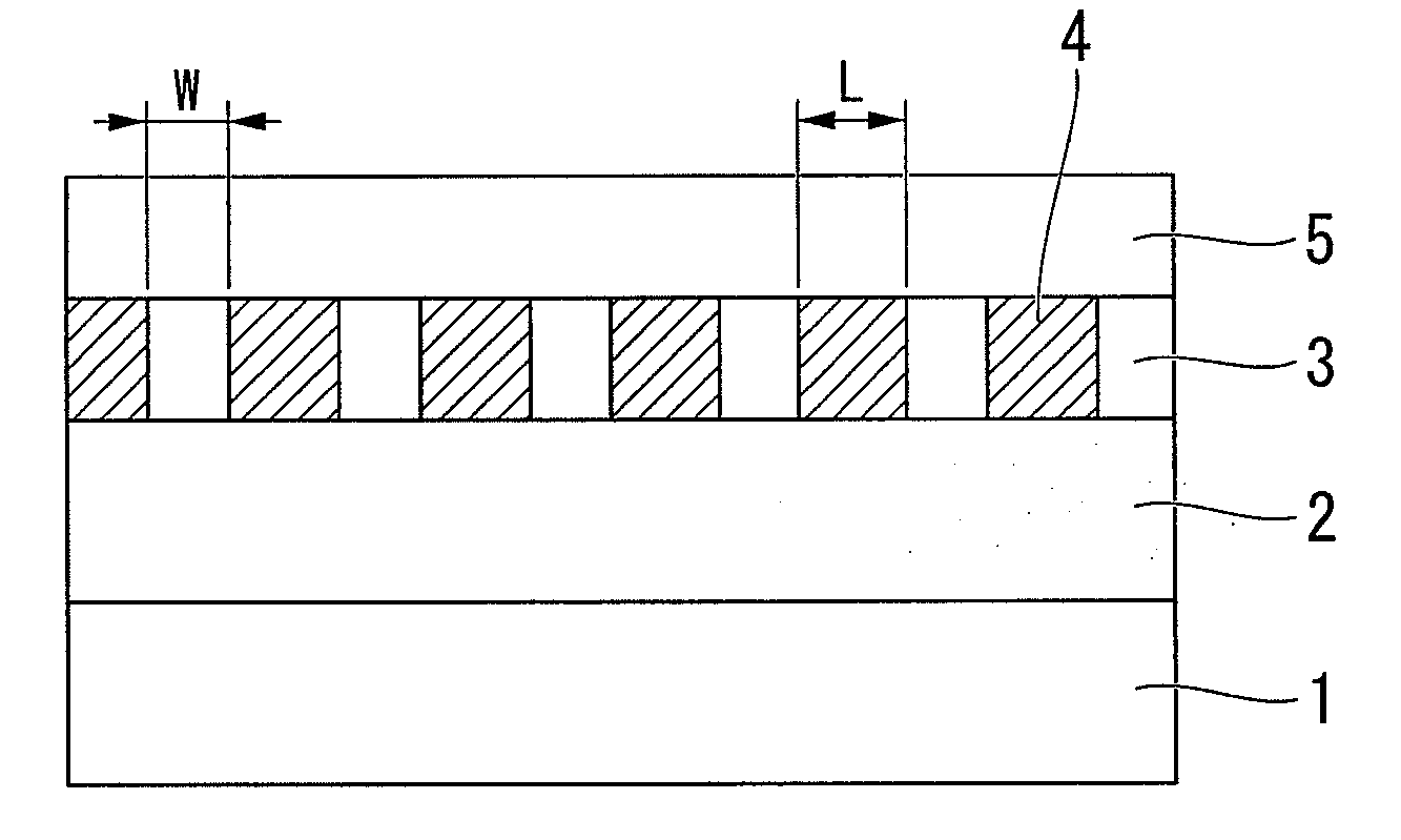
[0092]A vacuum chamber, herein a HD glass substrate was set, was vacuumed at 1.0×10⁻⁵ Pa or less in advance. The glass substrate was made of a crystallized glass that included Li2Si2O5, Al2O3—K2O, Al2O3—K2O, MgO—P2O5, and Sb2O3—ZnO as components. The outer diameter was 65 mm; the inner diameter was 20 mm; the average surface roughness (Ra) was 2 angstrom (unit: Å; and equal to 0.2 nm).

[0093]On the glass substrate, using the DC sputtering, FeCoB as a soft magnetic layer; Ru as an intermediate layer; and 70Co-5Cr-15Pt-10SiO2 alloy as a magnetic layer were laminated in order; and, using the P-CVD method, a C (carbon) protective layer, and a fluorine-based lubricant film were further laminated as thin films thereon in order. With regard to the thickness of each layer, the FeCOB soft magnetic layer was 600 Å; the Ru intermediate layer was 100 Å; the magnetic layer was 150 Å; and the C (carbon) protective layer was 4 nm on average.

[0094]A UV-curable resin was coated thereon in a thickness...

examples 2 to 22

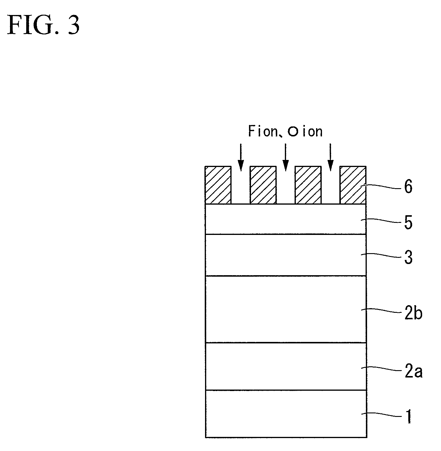
[0098]Magnetic recording media were produced in the same manner as Example 1. In this case, the type of gas used for generating the reactive plasma, the applied power, the reaction pressure, and the reaction time was modified as shown in Table 1. In Examples 2 to 22, the X-ray diffraction analysis was conducted with respect to the portion of the magnetic layer treated with reactive plasma. In the results, a signal derived from Co disappeared. On the other hand, a signal derived from cobalt fluoride was not observed, and it was confirmed that the portion was formed into an amorphous structure in all Examples 2 to 22.


PUM

PropertyMeasurementUnit
Fractionaaaaaaaaaa
Fractionaaaaaaaaaa
Forceaaaaaaaaaa

Abstract

The present invention aims to provide a method of producing a magnetic recording medium which is a method of producing a magnetic recording medium having a magnetically-separated magnetic recording pattern, the method including: forming a magnetic layer on a non-magnetic substrate; then exposing a surface of the magnetic layer partially to reactive plasma, or a reactive ion generated in the plasma to amorphize the portion of the magnetic layer.

Description

TECHNICAL FIELD[0001]The present invention relates to a method of producing a magnetic recording medium, and a magnetic recording and reading device where the magnetic recording medium or the magnetic recording and reading device are used in a hard disk device or the like.BACKGROUND ART[0002]In recent years, not only has the applicability of magnetic recording devices such as a magnetic disk device, flexible disk device, or magnetic tape device been remarkably broadened, and its importance has been increased, but the recording density of a magnetic recording medium used in such a device has also been remarkably improved. In particular, the area density has been strikingly increased since an MR head and the PRML technique were introduced. Recently, a GMR head, TMR head, etc. have been introduced, and the area recording density has been continuously increased at the rate of about 100% per year. Achievement of higher recording density is still sought in developing such a magnetic recor...

Claims


Application Information

Patent Timeline
IPC IPC(8): G11B21/02G11B5/84
CPCG11B5/855H01F41/34
Inventor FUKUSHIMA, MASATOSAKAWAKI, AKIRASASAKI, YASUMASA
Owner SHOWA DENKO KK
Why Eureka
Try Eureka