Electrospun Scaffolds And Methods Of Generating And Using Same

Inactive Publication Date: 2010-07-08
TECHNION RES & DEV FOUND LTD
View PDF3 Cites 46 Cited by
  • Summary
  • Abstract
  • Description
  • Claims
  • Application Information

AI Technical Summary

Benefits of technology

[0056]Unless otherwise defined, all technical and/or scientific terms used herein have the same meaning as commonly understood by one of ordinary skill in the art to which the invention pertains. Although methods and materials similar or equivalent to those described herein can be used in the practice

Problems solved by technology

The design of scaffolds that mimic the biological functions of the extracellular matrix, without

Method used


Image

  • Electrospun Scaffolds And Methods Of Generating And Using Same
  • Electrospun Scaffolds And Methods Of Generating And Using Same
  • Electrospun Scaffolds And Methods Of Generating And Using Same

Examples


example 1

Generation of PCL Electrospun Scaffolds

[0175]Materials and Experimental Procedures

[0176]Electrospinning of Scaffolds

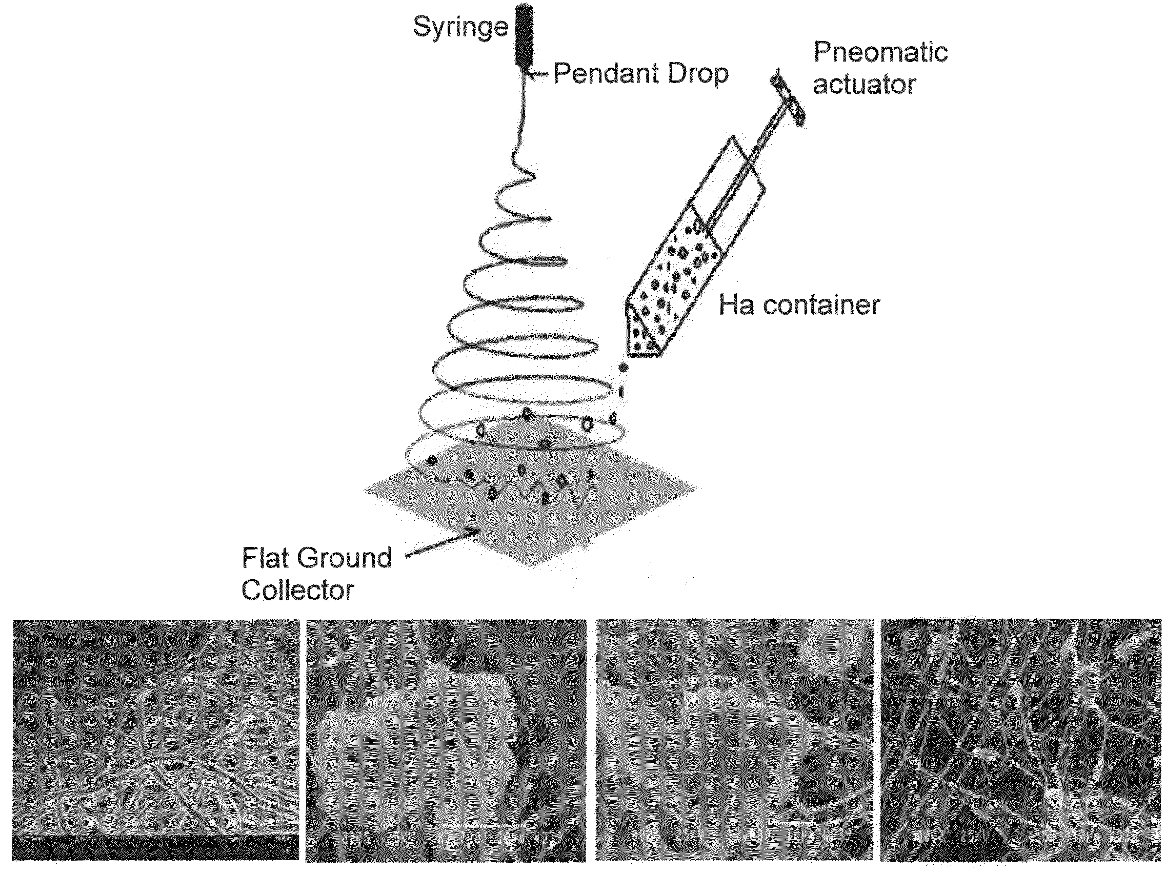
[0177]Poly (e-caprolactone) (PCL), a biodegradable polyester, with an average molecular weight of 80 kDa (Aldrich, USA) was dissolved in chloroform to obtain 10% wt. solution. The polymer solution was delivered at a constant flow rate to a metal capillary connected to a high voltage (13 kV). A fluid jet was ejected from the capillary. As the jet accelerated toward a grounded collector, the solvent evaporated and charged polymer fiber was deposited on a collector in the form of a non-woven scaffold. Hydroxylapatite (HA) particles (about 0.5 μm to 8 μm in diameter), dispersed in aqueous solution, were spread during the deposition process through a pneumatic setup located beyond the spinning apparatus (FIG. 2A).

[0178]The non-woven scaffold was cut in round shapes (0.5 mm) to fit a single well of a 96 well plate, sterilized (with oxygen plasma and antibiotics), washed (wit...

example 2

Generation of PCL / Gelatin Electrospun Scaffolds, Analysis and In Vivo Use

[0188]Materials and Experimental Procedures

[0189]Electrospinning of Scaffolds

[0190]PCL (approximately 80 kDa, Aldrich, USA) and acid Gelatin (Nitta Gelatin, Japan) were dissolved together (at a 1:1 ratio) in fluorinated alcohol of 2,2,2-trifluoroethanol (TFE) to give 9% and 12% solutions (w / v). The 9% solution was extruded from a 5 ml syringe connected to a hypodermic needle (bore size 0.6 mm; flow rate 3 ml / hr). The strength of the electrostatic field was 0.8 KV / cm. The electrospun nanofibers were deposited onto a grounded collector in the form of a non-woven sheet. Hydroxylapatite (HA) particles (about 0.5 μm to 8 μm in diameter), dispersed in aqueous solution, were spread during the deposition process through a pneumatic setup located beyond the spinning apparatus.

[0191]The end stage product size was 35×35×1.6 mm which was further cut into circular shapes (8 mm diameter) to fit into 24 well tissue culture pl...

example 3

Generation of Scaffolds for Connective Tissue Regeneration

[0218]Bone marrow derived MSCs will be selected in culture for their chondrogenic lineage using chondrogenic markers (such as alcian blue staining and collagen type II immunohistochemistry). These cells will be seeded in the different electrospun scaffolds (as explained in detail in Example 2 hereinabove) and will be examined for their potential to form cartilage. Formation of cartilage will be examined in vivo in ectopi subcutaneous animal models and in joint cartilage defect.


PUM

PropertyMeasurementUnit
Pore sizeaaaaaaaaaa
Diameteraaaaaaaaaa
Diameteraaaaaaaaaa

Abstract

A porous scaffold is disclosed, the porous scaffold comprising electrospun polymeric nanofibers, wherein an average diameter of a pore of the porous scaffold is about 300 μm is disclosed. An average diameter of the polymeric nanofibers ranges from about 100 to 400 nm. The scaffold may comprise a plurality of particles, the particles being greater than about 1 μm in diameter. Methods of fabricating scaffolds, methods for generating tissue and methods of using scaffolds for tissue reconstruction are also disclosed.

Description

FIELD AND BACKGROUND OF THE INVENTION[0001]The present invention, in some embodiments thereof, relates to an electrospun scaffold comprising polymeric nanofibers and particles and, more particularly, but not exclusively, to the use of same for bone or connective tissue regeneration.[0002]The need for bone repair is one of the major concerns of regenerative medicine. The key step in the modern approach of bone tissue engineering is the design and fabrication of porous three dimensional (3D) scaffolds. These 3D scaffolds serve as temporary artificial extracellular matrices, accommodating cells and supporting three-dimensional tissue regeneration. In order to achieve these goals, the scaffold's surface chemistry must be suitable for cell attachment and the pore size must allow cellular proliferation. The design of scaffolds that mimic the biological functions of the extracellular matrix, without eliciting an immunological reaction, is a major challenge in tissue engineering and bone re...

Claims


Application Information

Patent Timeline
IPC IPC(8): A61K33/42A61F2/00A61K35/12A61P19/00A61P43/00
CPCA61L27/46A61L27/56Y10S977/795A61L2400/12C08L67/04A61P19/00A61P43/00
Inventor SROUJI, SAMERZUSSMAN, EYALLIVNE, ERELLA
Owner TECHNION RES & DEV FOUND LTD
Why Eureka
Try Eureka