Thermodynamically shielded solar cell

a solar cell and thermal shielding technology, applied in the field of solar cells, can solve the problems of low efficiency of solar cells and inability to compete with fossil fuels, and achieve the effects of minimising radiative losses, reducing conductive heat loss, and reducing solar energy consumption

Inactive Publication Date: 2010-07-29
SOLAR CASCADE
View PDF10 Cites 2 Cited by
  • Summary
  • Abstract
  • Description
  • Claims
  • Application Information

AI Technical Summary

Benefits of technology

[0005]The invention under study is directed towards a system and a method for effectively improving the efficiency of solar cells. A further object of the invention is to present the most efficient solar cell for energy production known to man. An even further object of the invention is to reduce the unit production cost associated with solar photovoltaic setups.
[0009]It is also true that some of the photons with E>NB1 will not get absorbed, because they are simply unable to find the valence electron and interact with it. This fraction is not influenced by the band gap, however. The number of missed E>NB1 is a function of the concentration of the ion / atom / molecule species with the valence electron N1 and the scattering cross section of this electron. Also lattice packing density of the material, temperature etc. may have some effect. In one aspect of the invention the fraction of missed E>NB1 in the semiconductor layer is minimised. This group of unabsorbed photons with E>NB1 is further added to the secondary photon population.
[0012]It is currently easier to collect the energy of photons as photocurrent in accordance with the invention. Therefore it is an object of the invention to provide thermodynamic conditions for the solar cell in which secondary photon production and capture is maximised and secondary phonon production, i.e. temperature of the solar cell is controlled accordingly. Firstly it is in accordance with the invention to prevent the transfer of energy from the solar cell by means of phonon transmission. This is because when the gas surrounding the solar cell heats up, this energy is literally lost as ‘hot air’. Therefore any air or gas that is in contact with the solar cell is removed entirely or partially in accordance with the invention in one aspect of the invention. In one aspect of the invention, the solar cell is placed in a vacuum, and therefore heat loss by convection is minimised in this embodiment. The solar cell should not be in contact with any solid body either, apart from electric wires etc. needed for current collection. All contact with solid bodies should be heat insulated in the best way possible, thereby avoiding heat transfer by phonon-phonon interaction at a solid surface, i.e. conduction. When heat loss by conduction and convection is minimised or avoided, the solar cell will become hot in accordance with the invention.
[0025]In addition and with reference to the aforementioned advantage accruing embodiments, the best mode of the invention is considered to be a tandem solar cell of Si and InSb enclosed in a vacuum container to minimise convective heat losses. Incident sunlight is focused by a lens to a dispersing element that disperses the sunlight into the vacuum container and on to the Si layer that is facing the incident side of sunlight. The vacuum container has reflective foil on the inside to reflect retransmitted photons and thereby minimise radiative losses. InSb layer is behind the Si layer. The semiconductors are suspended with metal wires, minimising conductive heat losses, which may comprise the electrical contacts to the load or the DC inverter.

Problems solved by technology

The efficiency of solar cells is currently so low, that solar energy has not been competitive against fossil fuels during low energy prices.

Method used


Image

  • Thermodynamically shielded solar cell
  • Thermodynamically shielded solar cell
  • Thermodynamically shielded solar cell

Examples


embodiment 10

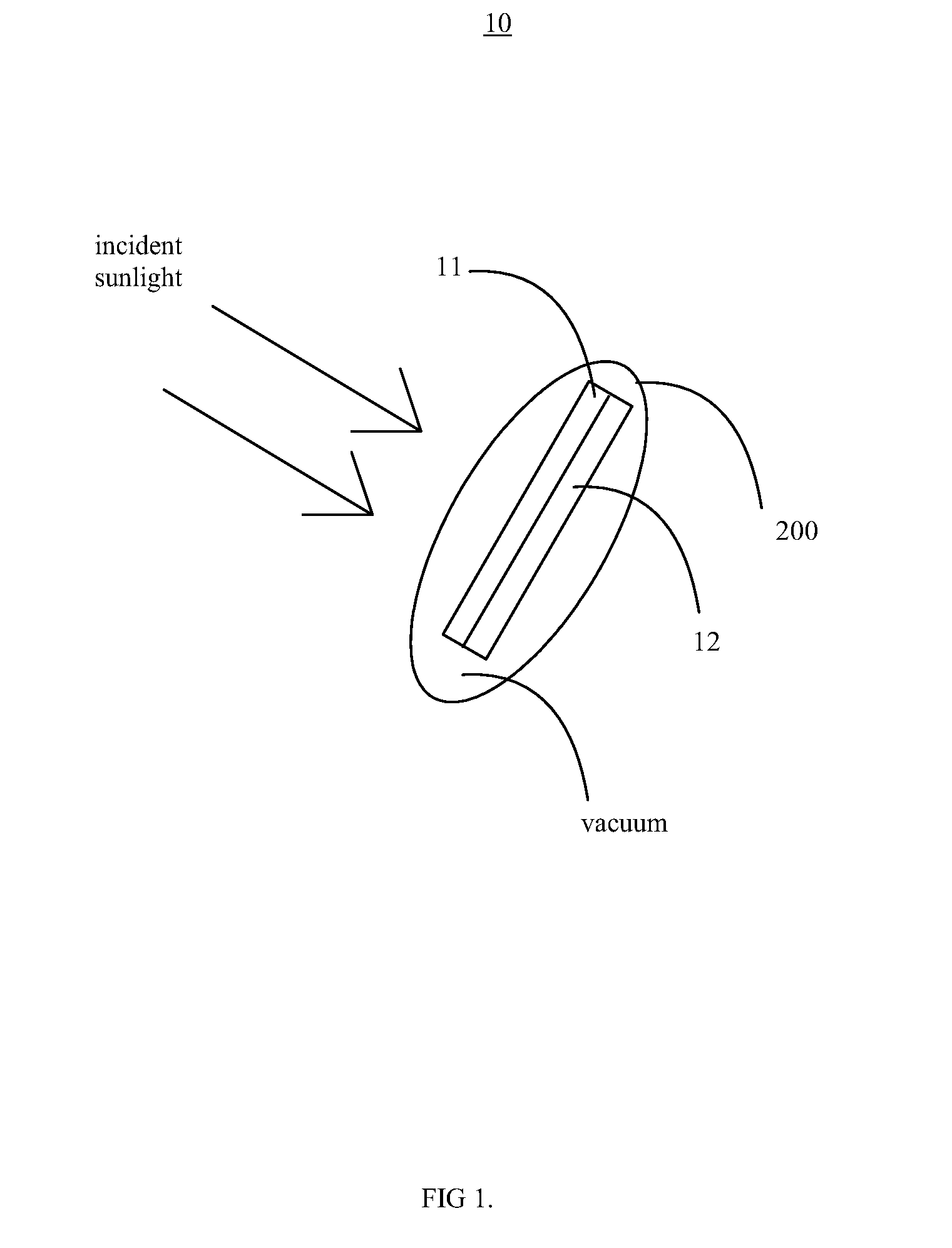
[0035]FIG. 1 shows a very simple embodiment of the inventive solar cell embodiment 10. A tandem solar cell with semiconductor layers 11 and 12 is enclosed in a casing or a membrane 200 that is transparent to solar light.

[0036]The semiconductor layers 11 and / or 12 may be composed of any material capable of photoelectric effect. For example the semiconductor layer 11, or any subsequent layer mentioned in this application (12, 13, 14, 15, 16, 17, layer 1, layer 2) may contain Si (Silicon), polycrystalline silicon, thin-film silicon, amorphous silicon, Ge (Germanium), GaAs (Gallium Arsenide), GaAlAs (Gallium Aluminium Arsenide), GaAlAs / GaAs, GaP (Gallium Phosphide), InGaAs (Indium Gallium Arsenic), InP (Indium phosphide), InGaAs / InP, GaAsP (Gallium Arsenic Phosphide) GaAsP / GaP, CdS (Cadmium Sulphide), CIS (Copper Indium Diselenide), CdTe (Cadmium Telluride), InGaP (Indium Gallium Phosphide) AlGaInP (Aluminum Gallium Indium Phosphide), InSb (Indium Antimonide), CIGS (Copper Indium / Galliu...

embodiment 20

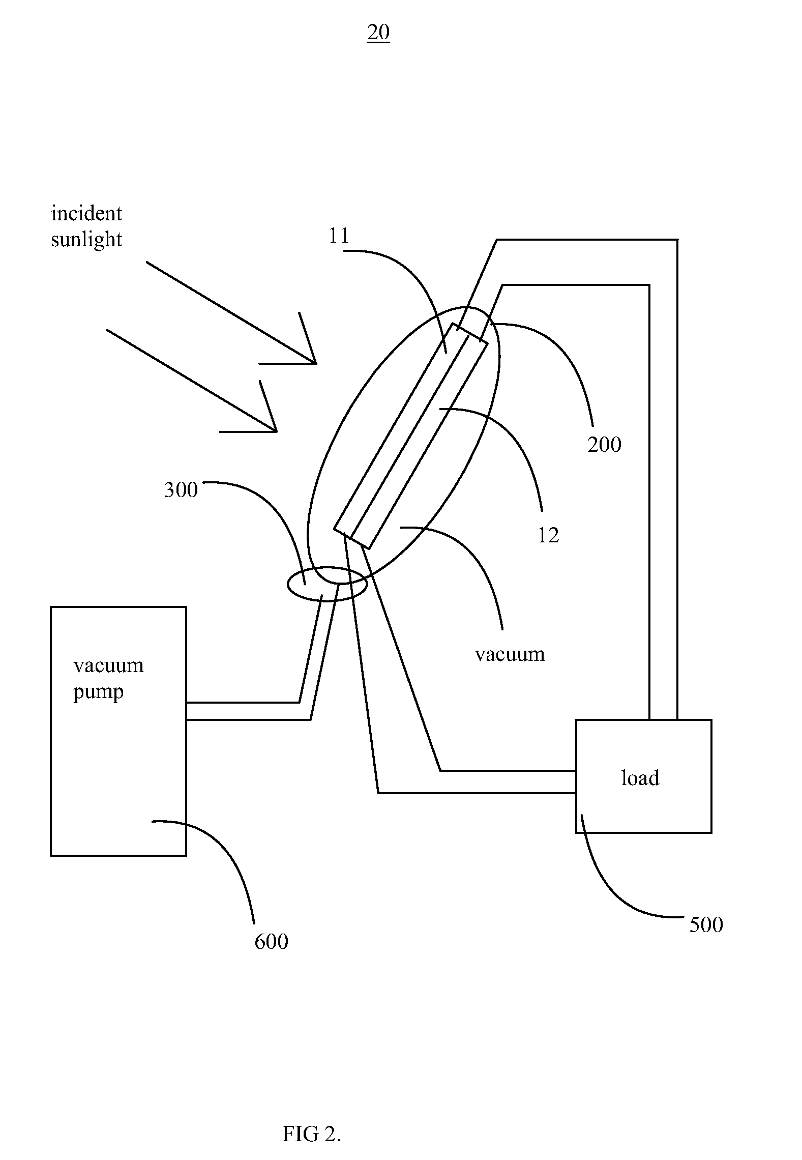
[0048]FIG. 2 shows an embodiment 20 of the solar cell in accordance with the invention, where the solar cell is used to power a load 500. The load 500 can be any device requiring electricity as energy, a energy storage device such as a battery or the electric grid itself. The photocurrent is collected from the semiconductor materials 11 and 12 to the load by electrical wires. Ideally the wires for the photocurrent collection should be made small and insulated, to minimise conductive and / or convective losses.

[0049]In some embodiments the casing and / or membrane 200 also incorporates a vent 300. In some embodiments the vent 300 may also incorporate a thermostat. In most embodiments of the invention the solar cell is similar to embodiment 10 explained before, and to save repetition it is noted that all embodiments 10, 20, 30, 40, 50, 60 and 70 may be freely permuted and changed and features from one embodiment to the other can be transferred in accordance with the invention.

[0050]A vacu...

embodiment 30

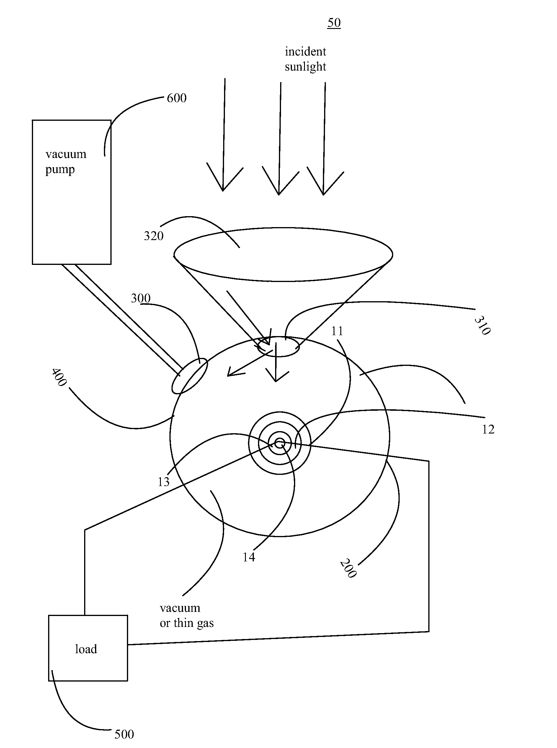
[0056]FIG. 3 displays an embodiment 30 of the inventive solar cell, where optical concentration devices and radiative, conductive and convective shielding are used to maximise photon entrapment in the casing and / or membrane 200.

[0057]The solar cell system comprises a focusing element 320, such as a lens or a mirror that is used to focus the incident solar light to a smaller area, thereby increasing flux in that area. The focused solar light is directed to an opening into the casing 200 for housing the photovoltaic cell system with semiconductor materials 11, 12. In some embodiments this opening may be installed with a ray diverging element 310 that spreads the solar light from the focused area to a wider area as the solar light passes through it. In some embodiments the diverging element 310 is a prism, mirror or a lens. Typically the elements 320, 310 are arranged so that a maximum photon collection area is obtained, and the photons are spread out across the entire surface of the p...


PUM


Abstract

The invention relates to solar cells. More particularly, the invention relates to arrangements and methods to increase the efficiency of solar cells.The methods and arrangements of the invention allow to increase the efficiency of solar cells (11, 12, 13, 14) by trapping photons into the photovoltaic system by thermodynamic shielding based on at least one of the following: conductive shielding, radiative shielding (20, 21, 22, 400, 410, 411) and / or convective shielding. The best mode of the invention is considered to be a tandem solar cell of Si (11) and InSb (12) enclosed in a vacuum container (200) to minimise convective heat losses. Incident sunlight is focused by a lens (320) to a diverging element (310) that disperses the sunlight into the vacuum container (200) and on to the Si (11) layer that is facing the incident side of sunlight. The vacuum container has reflective foil (400, 410, 411) on the inside to reflect retransmitted photons and thereby minimise radiative losses. InSb layer (12) is behind the Si layer (11). The semiconductors are suspended with metal wires, minimising conductive heat losses, which may include the electrical contacts to the load (500) or the DC inverter.

Description

TECHNICAL FIELD OF INVENTION[0001]The invention relates to solar cells. More particularly, the invention relates to arrangements and methods to increase the efficiency of solar cells.BACKGROUND[0002]The efficiency of solar cells is currently so low, that solar energy has not been competitive against fossil fuels during low energy prices. Due to this many technologies have been proposed to make solar cells more efficient and thus increase the competitiveness of solar energy in the global marketplace.[0003]EP 1724841 A1 describes a multilayer solar cell, wherein plural solar cell modules are incorporated and integrally laminated, so that different sensitivity wavelength bands are so that the shorter the centre wavelength in the sensitivity wavelength band is, the more near the module is located to the incidental side of sunlight. This document is cited here as reference.[0004]Optical concentrators, such as lenses and mirrors are known in the art, please see Solar Electricity, Thomas M...

Claims


Application Information

Patent Timeline
Patent Type & Authority Applications(United States)
IPC IPC(8): H01L31/00
CPCY02E10/52H01L31/0547H01L31/0521
Inventor VAANANEN, MIKKO
Owner SOLAR CASCADE
Why Eureka
Try Eureka