
Process for producing metal film, metal film and use of the metal film

Active Publication Date: 2010-09-16
ORMON CORP
View PDF12 Cites 9 Cited by
  • Summary
  • Abstract
  • Description
  • Claims
  • Application Information

AI Technical Summary

Benefits of technology

[0009]The present invention is accomplished in view of the problems, and an object of the present invention is to provide (i) a process for producing a metal film with which process a metal film and a metal pattern can be formed, at low cost, on an arbitrary substrate, and by which process the problem involved in a sputtering method can be solved, (ii) a metal film, and (iii) use of the metal film.
[0045]An electric device and an electronic device of the present invention include a metal film produced by the process for forming a metal film of the present invention. The metal film is formed uniformly on an arbitrary substrate with a high adhesiveness, and has a thickness between several tens to nanometers and several hundreds of nanometers. It is also possible to control the resistance value thereof from a low resistance value to a relatively high resistance value. The metal film has an excellent function particularly as a transparent conductive film.

Problems solved by technology

Meanwhile, a sputtering method involves a problem that it is difficult to enlarge a transparent conductive film because of an insufficient in-plane uniformity of a source material.
As a result, while it is easy to collect the target of the source material, a problem of very poor use efficiency arises in the material deposited at the periphery because it has to be chipped off for collection.
This is also seen as a problem in relation to the depletion of indium that is used widely for forming a transparent conductive film, and thus an alternative technology (environment-responsive technology) to a sputtering method is desired.
Furthermore, a metal film formed by a sputtering method has other problems as well.
For example, the metal film formed by a sputtering method is susceptible to break.
In addition, a metal film formed by a sputtering method is poor in production efficiency, because it necessitates an annealing process at a high temperature.
However, a photolithography method involves problems of expensive equipment and low throughput.

Method used


Image

  • Process for producing metal film, metal film and use of the metal film
  • Process for producing metal film, metal film and use of the metal film

Examples


examples

Preparation of a Primer Composition and Formation of an Organic Film

[0182]In order to provide a primer composition, a chemical liquid in which compounds shown in Table 1 were mixed with one another in such a manner that contents of the compounds amount to 100% by weight was prepared and applied onto glass slides by a spin coat method. Then, with use of an ultraviolet irradiation device (PL 16-110, manufactured by SEN Lights Corporation), the glass slides were irradiated with an ultraviolet ray for 20 minutes so as to form the organic films A to I thereon.

[0183]As an addition polymerizable compound including three or more reactive groups, pentaerythritol triacrylate (product name: PE-3A, manufactured by Kyoeisha Chemical Co., Ltd.) was used.

[0184]As an addition polymerizable compound including an acid group, 2-acryloyloxyethyl phthalic acid (product name: HOA-MPL, manufactured by Kyoeisha Chemical Co., Ltd.), 2-acryloyloxyethyl hexahydrophthalic acid (product name: HOA-HH, manufactur...

example 8

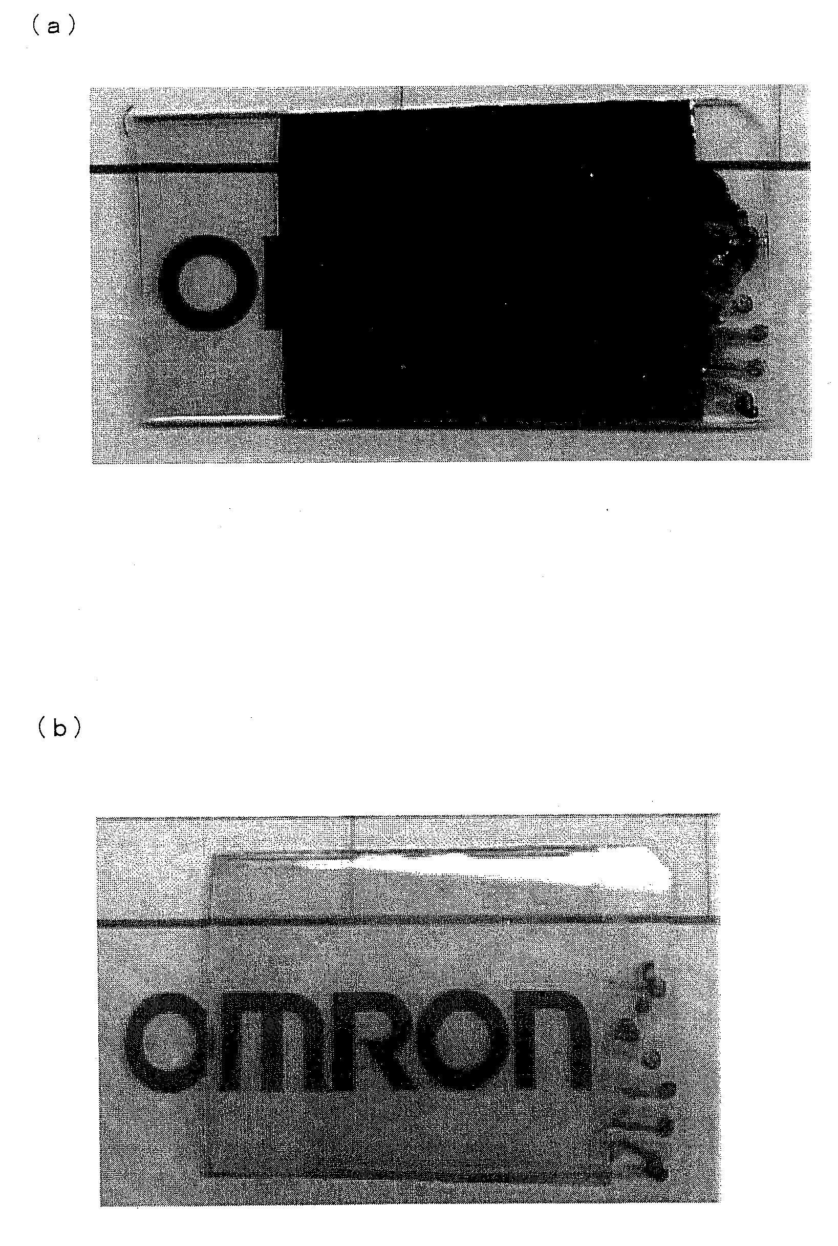
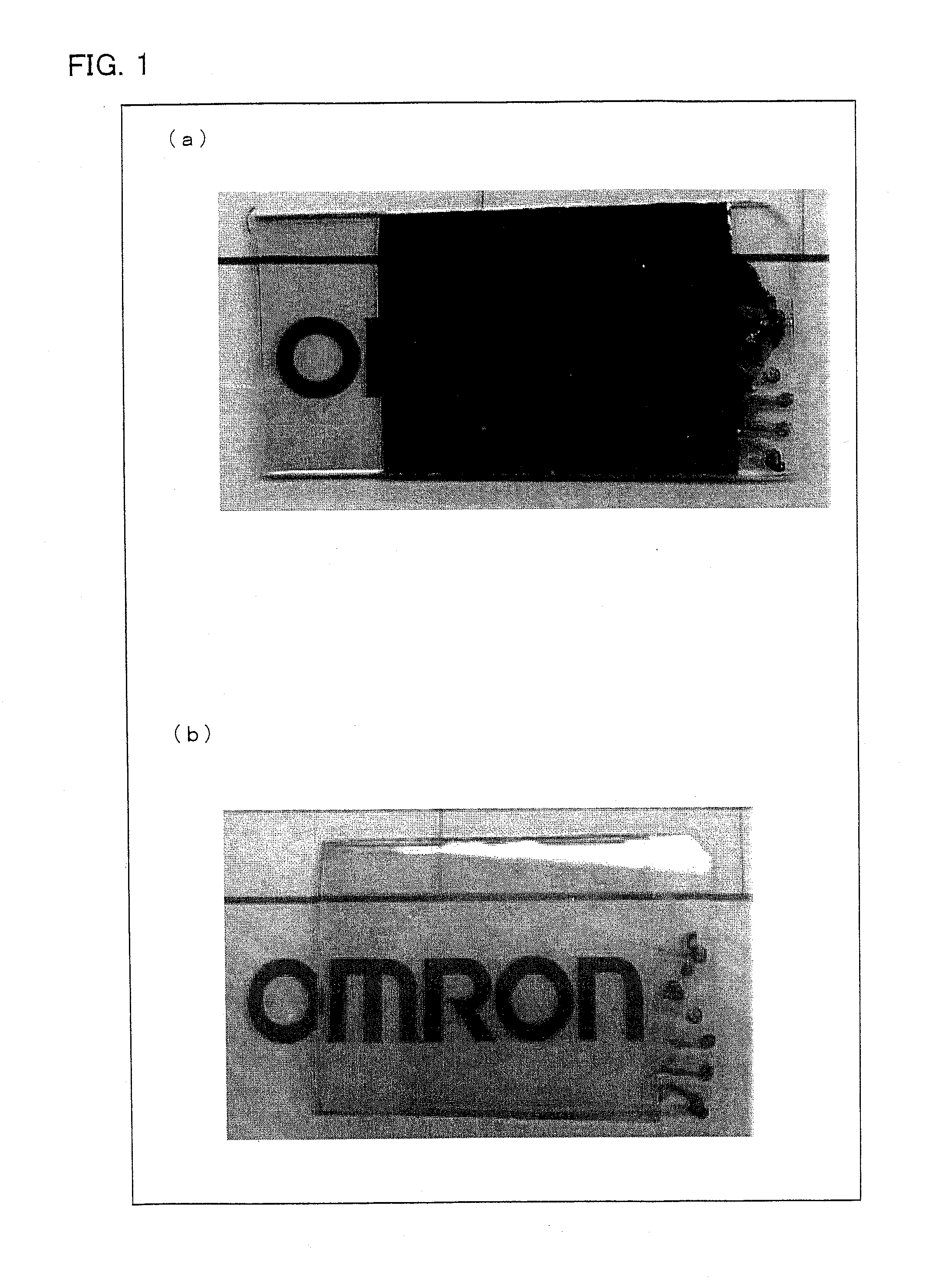
[0206]The glass substrate used in Examples 2 and 3, to which a primer composition had been applied, was irradiated with an ultraviolet ray at 20 mW / cm for 2400 seconds by an UV irradiation device (PL16-110, manufactured by SEN Lights Corporation) so as to harden the primer composition. Then, the glass substrate was held in an 8M KOH at 40° C. for 10 minutes, and washed with water. After that, the glass substrate was held in a 100 mM ZnCl2 aqueous solution at 25° C. for 15 minutes, and then washed with distilled water. Subsequently, the substrate was held in an aqueous solution, in which 25 mM Na2CO3 and 25 mM NaHCO3 were mixed in the volume ratio of 6:4, at 50° C. for 15 minutes. As a result, a lacteous zinc oxide film (with a thickness of approximately 100 nm) with a surface resistance of 5 MΩ / square and a transmissivity of 40% was obtained.

example 9

[0207]Conditions of the metal salt generating step were studied using the organic film B used in Example 2.

[0208]A metal film was obtained by subjecting the glass slide, on which the organic film B had been formed, to the following steps:

[0209](1) As shown in Table 2, the following experimental groups were prepared: (i) The glass substrate was dipped in a 5 M potassium hydroxide aqueous solution at 40° C. and held for 10 minutes; (ii) The glass substrate was dipped in a M potassium hydroxide aqueous solution at 40° C. and held for 5 minutes; (iii) The glass substrate was dipped in a 5 M potassium hydroxide aqueous solution at 40° C. and held for 2 minutes; (iv) The glass substrate was dipped in a 5 M potassium hydroxide aqueous solution at 30° C. and held for minutes.

[0210](2) After the time mentioned in (1) had passed, the glass substrate was sufficiently washed in distilled water.

[0211](3) The glass substrate was dipped in a 100 mM of InCl3 aqueous solution at 25° C. and held for ...


PUM

PropertyMeasurementUnit
Shapeaaaaaaaaaa
Hydrophilicityaaaaaaaaaa
Surface activityaaaaaaaaaa

Abstract

The process of the present invention for producing a metal film includes: forming an organic film using a primer composition containing an addition polymerizable compound including three or more reactive groups, an acid group-including addition polymerizable compound, and a hydrophilic functional group-including addition polymerizable compound; forming a metal (M1) salt from the acid group; substituting the metal (M1) salt of the acid group with a metal (M2) salt by processing the organic film with a metal (M2) ion aqueous solution containing a metal (M2) ion having less ionization tendency than the metal (M1) ion; reducing the metal (M2) ion so that a metal film is formed on a surface of the organic film; and oxidizing the metal film. This provides (i) a process for producing a metal film and a metal pattern, at low cost, on an arbitrary substrate, (ii) a metal film, and (iii) use of the meta film.

Description

TECHNICAL FIELD[0001]The present invention relates to a process for producing a metal film, a metal film, and use of the metal film. In particular, the present invention relates to (i) a process for producing, at low cost, a metal film with a film thickness of tens of nanometers to hundreds of nanometers directly on an arbitrary resin film, (ii) a metal film produced by the process, and (iii) use of the metal film.BACKGROUND ART[0002]Transparent conductive laminates, in which a transparent conductive film is provided on an electrically insulating transparent substrate made of e.g. polyethylene terephthalate (PET) or glass, have been widely used as a material for forming electrodes and wires that are required to be transparent. Examples thereof include drive electrodes for display elements such as a liquid crystal display device or an electroluminescent element, window electrodes for photoelectric conversion elements such as a solar battery, a transparent electrode film for a coordin...

Claims


Application Information

Patent Timeline
IPC IPC(8): H01B1/02B05D5/12
CPCC23C18/06C23C18/08C23C18/14C23C18/2086C23C18/1678C23C18/1696C23C18/1893C23C18/1667Y10T428/31678Y10T428/31692Y10T428/31681C23C18/143C23C18/145
Inventor NAKAJIMA, SEIJIHAYASE, TETSUOMORI, TETSUYA
Owner ORMON CORP
Learn More