Heat-Managing Composite Structures

a composite structure and heat management technology, applied in the field of structural engineering, can solve the problems of high temperature, severe thermal gradient, high stress, and gas turbine engine components, and achieve the effects of high static and dynamic strength, effective management of intense thermal loading, and light weigh

Active Publication Date: 2010-09-23
UNIV OF VIRGINIA ALUMNI PATENTS FOUND
View PDF8 Cites 50 Cited by
  • Summary
  • Abstract
  • Description
  • Claims
  • Application Information

AI Technical Summary

Benefits of technology

[0009]The present invention provides novel structures that have high static and dynamic strength, that are light weight, and that are able to manage intense thermal loading effectively. They are therefore well suited to aerospace applications. Embodiments of the invention utilize the multifunctional behavior of cellular core panel structures to improve the performance of jet engine blades, disks, and blisks; rocket engines; and leading edges of orbital and / or hypersonic aerospace vehicles where high thermal fluxes and mechanical stresses can be encountered (for example, during re-entry).
[0010]Thus, embodiments of the invention include rocket engine nozzles and engine discs with simple curvatures; blades / vanes with twisted airfoil topologies; and leading edge structures for hypersonic vehicles. These structures are constructed from cellular core panels with either solid or sandwich-panel outer faces. In the latter configuration, the sandwich panel is arranged as a thermal (i.e., heat plate) spreading system. The cellular cores can be fabricated from solid or hollow struts and are arranged to maximize the support of dynamic and static stresses, and they facilitate cross-flow heat exchange with cooling gases. The structures can be fabricated by first creating a core substructure including an array of trusses that are either solid or hollow. When hollow trusses are employed, they may be in the form of conventional and / or micro heat pipes that are able to efficiently and rapidly transfer heat in their axial directions. Such truss arrays are flexible when free-standing, and they can be elastically or plastically distorted to fit onto a complexly curved surface without loss in ultimate mechanical or thermal performance. The array of trusses may be bonded to curved faces by diffusion bonding; brazing; other transient liquid phase bonding methods; welding of all types; or by any other convenient means of robust attachment.
[0011]In one approach, an embodiment of the present invention provides heat plates to spread heat uniformly across the surface of a structure. This heat is then transported, by predominantly conduction or convection, to a cellular lattice structure that also can be made of heat pipes (or conventional materials), where it is dissipated to a cooling flow. Alternatively, a thermal protection system is used to impede the flow of heat into the system described above. This reduces the heat flux that must be dissipated to the cooling flow.
[0012]In another approach, lattice-type structures are provided as lateral strain isolators so that thermal displacements created in hot regions of the system do not cause large stresses in other parts of the structure. This improves the cyclic thermal life of the structure.
[0013]Due to their open nature, various lattice materials can be designed to have low flow-resistant pathways in the structure. Manufacturing the struts of the lattice cores from high thermal conductivity materials increases the thermal conduction from a hot surface into the open lattice structure. This enables sandwich panels with cellular cores to function as highly efficient cross-flow heat exchangers while simultaneously providing mechanical strength to the overall structure. They are therefore excellent candidates for creating multifunctional structures combining load support and thermal management.
[0014]The heat pipe concepts disclosed herein can be extended to sandwich plate or lattice truss structures by applying wicking material to the webs of a perforated honeycomb or corrugated (prismatic) structure or to the inside of a hollow tube. In the former case, the addition of hermetic face sheets then creates a closed system which can be used to spread heat from hot regions of a plate type structure. In the case of heat pipes, on the other hand, the tubes can be configured as cellular lattice structures to form a structural core, and the addition of hermetic face sheets then creates a closed system which can be used to spread heat into an open lattice configuration. That heat can be easily removed by cross-flow heat exchange principles. In both cases, the resulting systems possess very high specific strength and very high thermal transport rates.

Problems solved by technology

For example, as a hypersonic vehicle travels through the earth's atmosphere, the high local heating and aerodynamic forces cause extremely high temperatures, severe thermal gradients, and high stresses.
Gas turbine engine components—particularly stator and rotor blades—also experience extremely high mechanical and / or thermal loading.
Such coatings, however, are not perfectly reliable in all cases, so the engine components must be able to continue functioning even after a portion of the TBC spalls.
This enables an increase in the operating temperature of the engine while maintaining the temperature of the blade material below that which results in service failure (by oxidation, hot corrosion or creep / fatigue), even when TBC spalling occurs.
The thermally insulating ceramic coatings applied on top of these layers reduce the blade metal surface temperature and therefore the rate of degradation during service.
Thus, these considerations present intricate design challenges to an aerospace engineer.

Method used


Image

  • Heat-Managing Composite Structures
  • Heat-Managing Composite Structures
  • Heat-Managing Composite Structures

Examples


Embodiment Construction

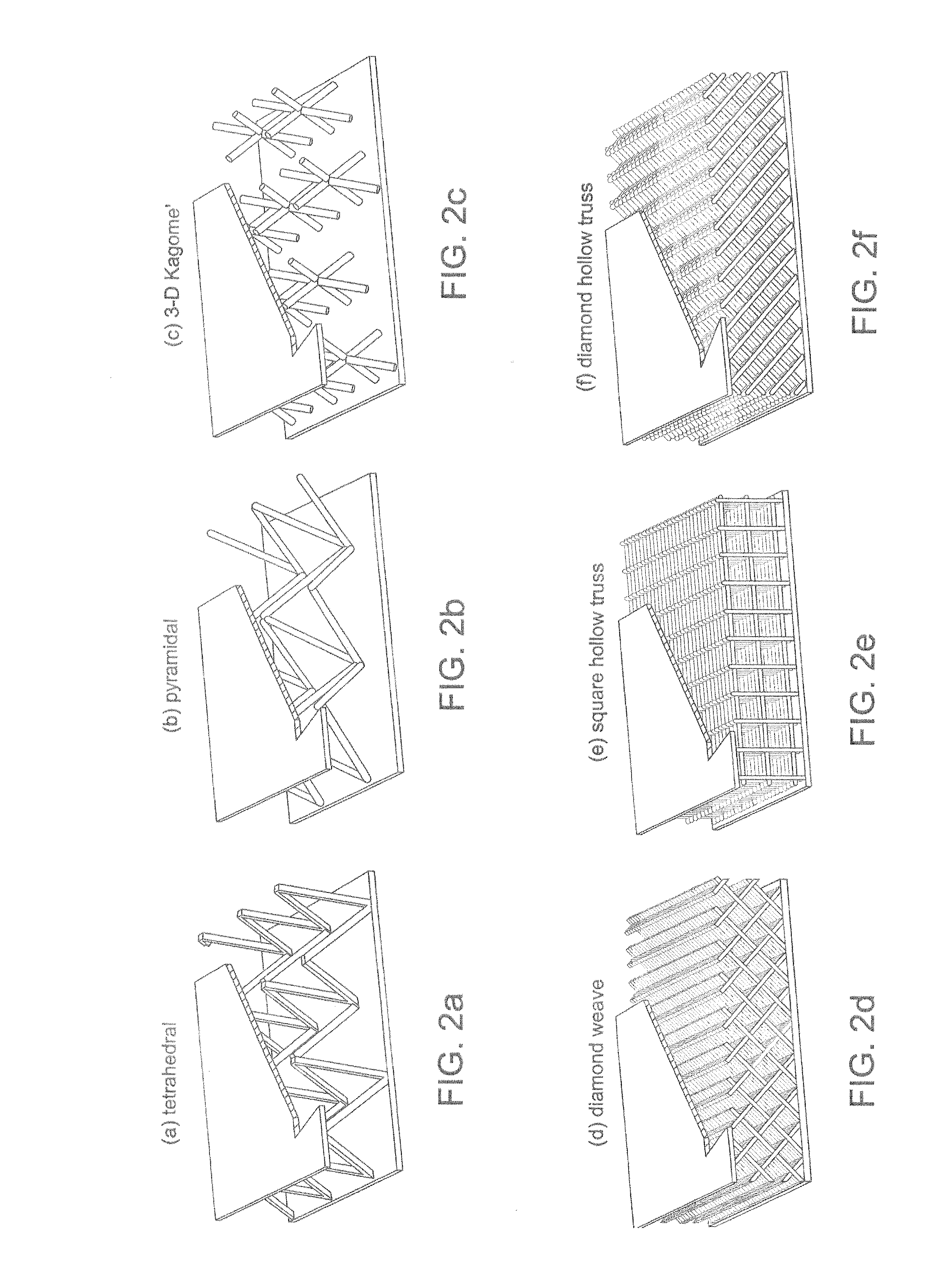
[0024]Structures according to the invention utilize thermal management concepts including heat plate and / or heat pipe concepts. Additionally, they utilize cellular and / or lattice-type, metal structural arrangements. Accordingly, it is beneficial to explain such concepts and structures before describing structural embodiments according to the invention which utilize them.

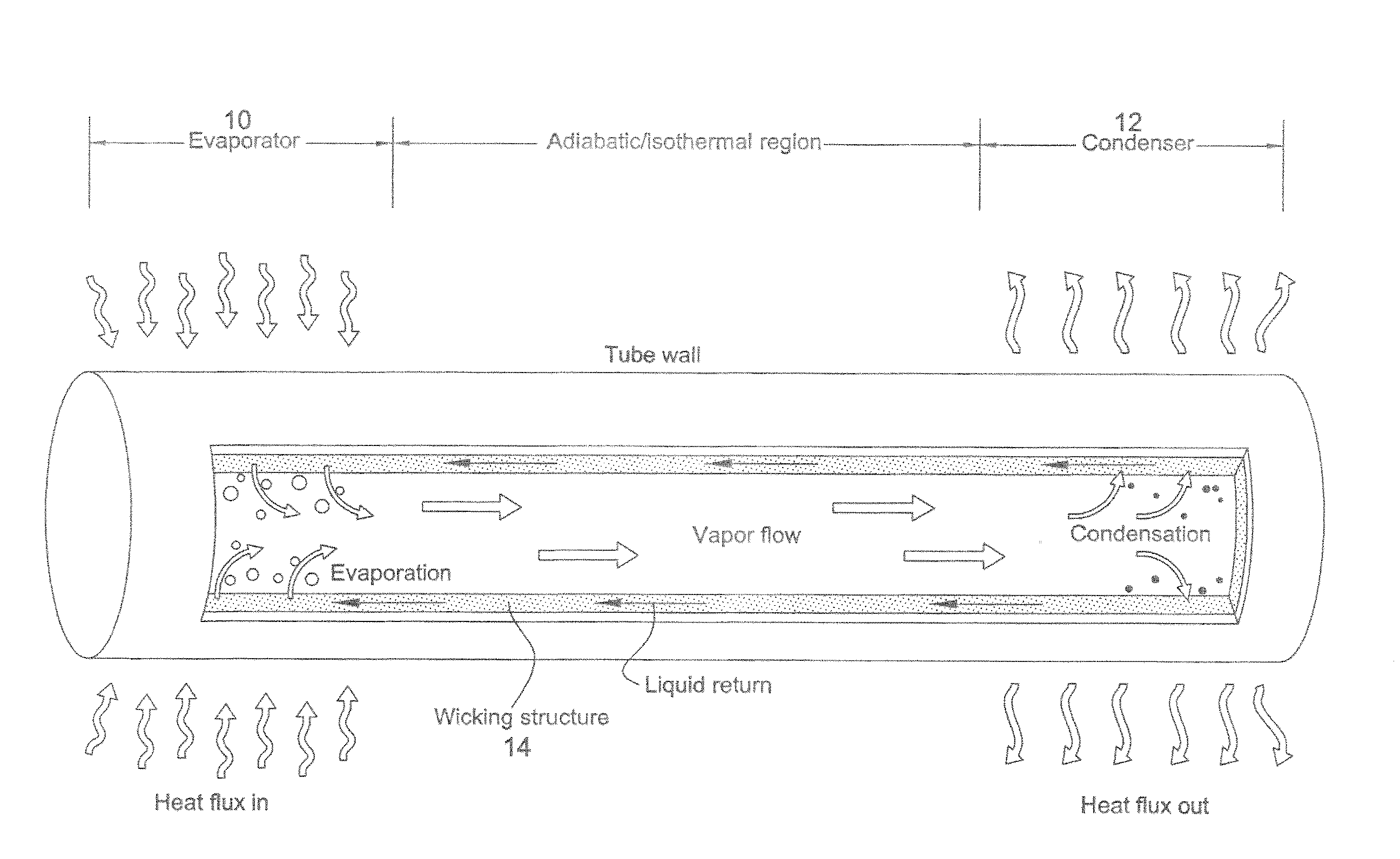
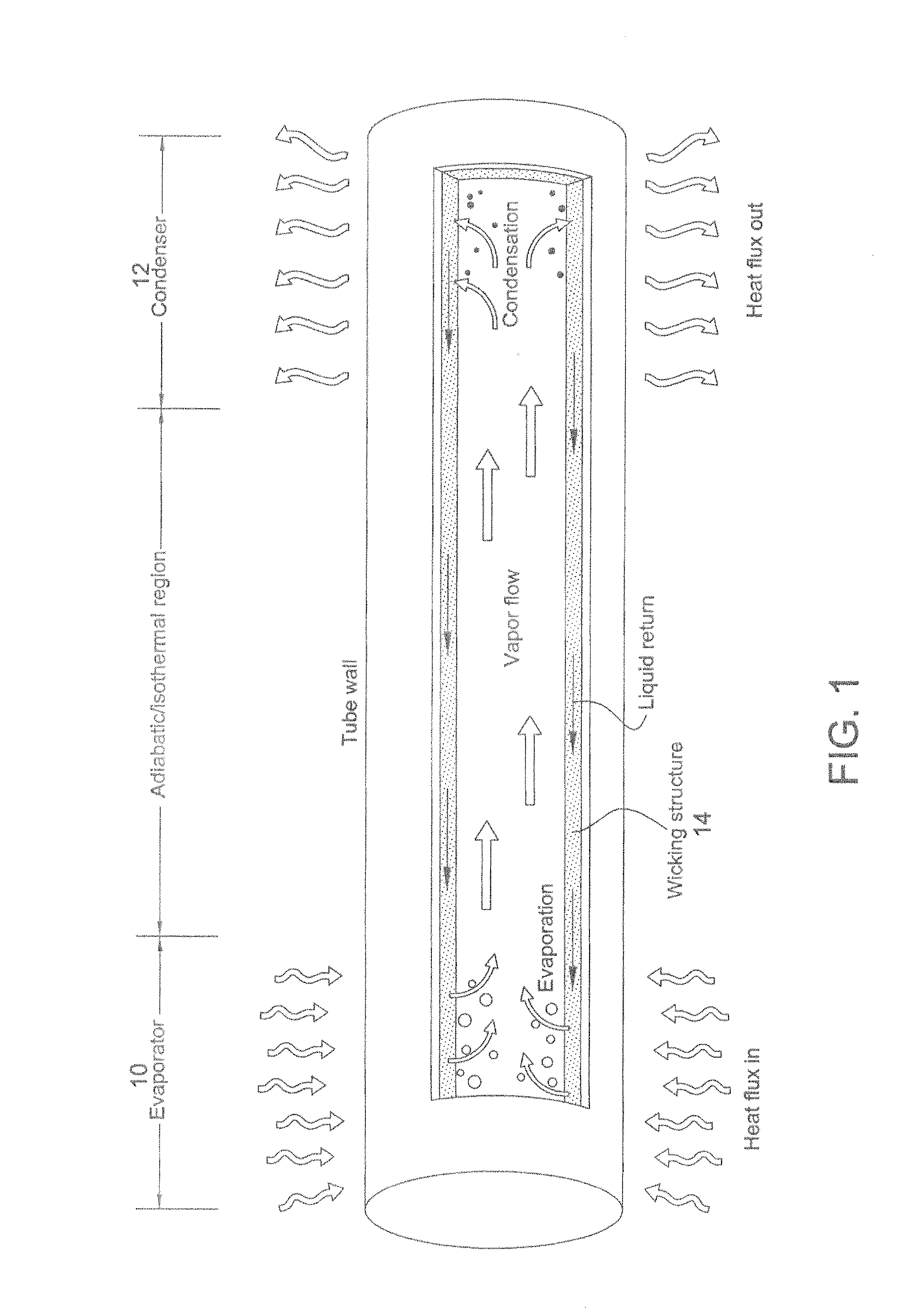
[0025]First, a heat pipe or heat plate is a sealed system which transfers heat nearly isothermally via the evaporation and condensation of a working fluid. For example, a basic heat pipe arrangement is illustrated schematically in FIG. 1. As illustrated, heat is absorbed in the hot region or evaporator portion 10 of the heat pipe, which causes working fluid contained therein to vaporize. Vaporized working fluid will thus hold the latent heat of vaporization. The evaporation results in a slight internal pressure differential within the heat pipe, which causes the vapor to flow rapidly from the evaporator region 10 to ...


PUM

PropertyMeasurementUnit
temperaturesaaaaaaaaaa
heat-aaaaaaaaaa
lattice structureaaaaaaaaaa

Abstract

Light-weight, heat-managing structures feature open-cell lattice, honeycomb, and/or corrugated (prismatic) arrangements in their substructures, combined with heat pipe/heat plate arrangements for managing heat to which the structures are subjected. The structures are well suited to aerospace applications and may be employed in the leading edge of wings or other airfoil-shaped components; gas turbine engine components; rocket nozzles; and other high-heat, high-stress environments.

Description

CROSS-REFERENCE TO RELATED APPLICATIONS[0001]This application is based on and claims priority benefit of U.S. provisional application No. 60 / 923,880 filed Apr. 17, 2007, the entire contents of which are incorporated by reference.FIELD OF THE INVENTION[0002]In general, the invention relates to structural engineering. More particularly, the invention relates to structures that are adapted to manage high heat loads as well as to handle large static and dynamic forces. The inventive structures are particularly suited for aerospace applications.BACKGROUND OF THE INVENTION[0003]Aerospace vehicles have many components that are subjected to high thermal and mechanical loading. For example, as a hypersonic vehicle travels through the earth's atmosphere, the high local heating and aerodynamic forces cause extremely high temperatures, severe thermal gradients, and high stresses. Stagnation regions, such as wing and tail leading edges and nose caps, are critical design areas. These regions expe...

Claims


Application Information

Patent Timeline
Patent Type & Authority Applications(United States)
IPC IPC(8): F28D15/00F28F13/18
CPCE04C2/34E04C2/3405E04C2/365E04C2002/3488E04C2002/3455E04C2002/3472E04C2002/345
Inventor WADLEY, HAYDN N.G.QUEHEILLALT, DOUGLAS T.
Owner UNIV OF VIRGINIA ALUMNI PATENTS FOUND
Why Eureka
Try Eureka